Ground Communications
Matt Gialich

We previously wrote about radio frequency (RF) links and link budgets, focused on the spacecraft design. Now let’s look at the other side of that link - ground stations.
Unlike the spacecraft components, deep-space capable ground stations don't fit the "new space" mold. Most are owned by government space agencies in their respective countries. This means we're not only trying something new from a technical standpoint, but we're also dealing with a business side that still operates through the lengthy proposal processes typical of government agencies. This was our first experience making "old space" work for us.
We definitely faced a learning curve. While flying Odin, we encountered various failures and difficulties throughout our ground network—from hardware issues to testing problems to configuration challenges. Odin provided a massive learning experience on the ground side. Without flying Odin, we wouldn't have learned these lessons, and if Odin accomplished nothing else, it revealed our shortcomings and gave us time to address them.
Deep Space is Different
NASA has accomplished so many impressive feats over the years that we often take their capabilities for granted, thinking “it can’t be that hard.” The Deep Space Network (DSN) - NASA’s system of long-range communication ground stations - is a perfect example. At AstroForge, we would gladly use the DSN if it aligned with our cost and schedule constraints. However, the DSN is already oversubscribed with NASA missions, making it difficult and expensive for a commercial company to access unless NASA sponsors the mission. Further, the integration time for DSN exceeded Odin’s development timeline and would have required additional overhead to meet a broader set of standards. While this might be worthwhile in the long term, our immediate need is to move forward quickly.
As a result, AstroForge relies on commercial ground stations for deep space communications and tracking. While commercial ground stations are plentiful and effective for satellites up to geosynchronous orbit (GEO), deep space operations have different requirements:
Large antennas with powerful amplifiers to transmit a long distance
Large antennas with sensitive, ideally cryogenically-cooled, low-noise amplifiers to receive a weak signal
Precise timing references to enable navigation using Doppler (frequency shift), often done using an atomic clock
Radios that support ranging, which measures distance to the spacecraft using a coherent sequence
Commercial options for dish antennas at least 50 feet across are limited. Many of these dishes belong to national agencies and are merely leased to commercial providers, creating complicated arrangements and a patchwork of connections. In some cases, we worked directly with antenna owners, while in others, we worked through ground networks already integrated with the antenna.
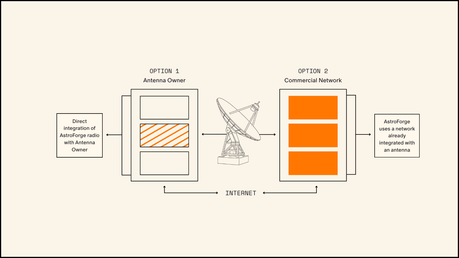
Currently, no single commercial network equivalent to the DSN exists for deep space missions. This is a known gap that several companies are striving to fill - Intuitive Machines, Cascade Space, KSAT, and SSC are all at various stages of developing cislunar-and-beyond capability. While building out their own complete ground stations, these companies typically partner with existing large antennas for immediate capability. As a result, when working with an antenna network, that network may not own or control the specific antenna we need, but instead be one of several organizations sharing that antenna.
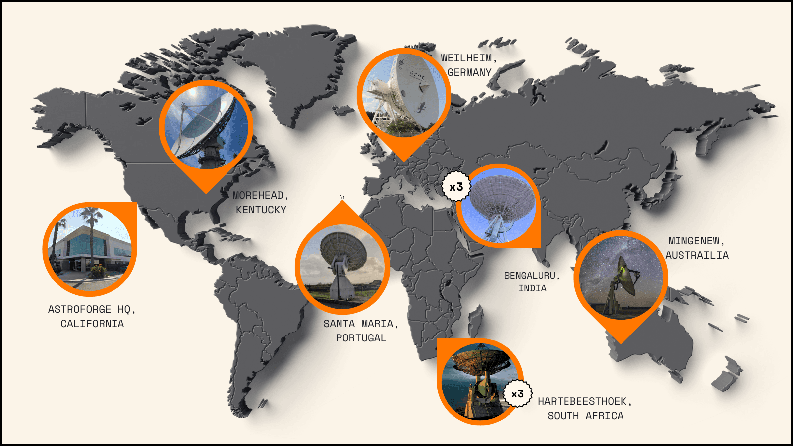
For Odin, we utilized 10 antennas across six locations in six countries. Accessing these sites required interfacing with five different companies, demanding extensive organization and testing, while creating numerous opportunities for miscommunications and errors. Half of these sites used AstroForge-owned radios, while the other half relied on the antenna owner’s radio or a third-party network radio. This arrangement supported Odin and will be our starting point for the DeepSpace-2 mission until new antennas become operational. DeepSpace-2 will benefit from more ground antennas across more locations, which we’ll explore further below.
Beyond the limited antenna selection, radio frequencies are regulated by international bodies (International Telecommunications Union) and national agencies (Federal Communications Commission or FCC in the United States). Each satellite must coordinate its radio frequencies based on its intended purpose. However, there's no specific category for “Commercial Deep Space” or even “Deep Space Operations,” forcing us to operate under “Space Research - Deep Space.” This lack of dedicated spectrum allocation for deep space commerce highlights just how groundbreaking AstroForge’s mission is - Odin received the first ever FCC license for commercial use of the deep space band.
Within the possible “Space Research — Deep Space” allocations, the limited selection of radios and other RF components restricted us to use S-band frequencies at ~2 GHz.
Larger antennas come with another tradeoff: they have narrower beams. Looking at half-power beam-width, which we described in our last post, a 50-foot antenna has a beam-width of just 0.6 degrees — about half the diameter of the moon in the night sky. The largest antenna we used for Odin had an even narrower beam-width of 0.3 degrees, making it critical to precisely track the spacecraft’s position in order to aim ground antennas correctly.
Launch
Although we separated from the rocket near Earth and began communications close to home, Odin’s trajectory headed away from Earth very quickly — within hours, we traveled past the GEO belt, further than most spacecraft venture. Within days, we reached the moon. This rapid departure caused our signal strength to decrease quickly, and with it our ability to command or receive data from Odin. During any anomaly, we had very little time to troubleshoot the issue from the ground.
Unlike Odin, satellites in Earth orbit have the advantage of remaining nearby even when problems arise. These satellites can be tracked using radars and telescopes even without direct communication. This proximity typically provides ample time to resolve issues. However, when you’re racing towards the moon at over 22,000 miles per hour as Odin did, this luxury disappears. All of this just means that we had very little margin for error, as our commissioning sequence was compressed into 4 days instead of the 4 weeks (or even 4 years) that some missions enjoy.
Testing a Ground Station
Ground stations have existing infrastructure that must communicate with our spacecraft via radio waves and with our Mission Operations Center (MOC) via the Internet. After selecting a ground station that meets our requirements on paper, how do we make sure it can do the job? To explain our testing process, let’s start with a look at the space-to-ground link (downlink), focusing specifically on its receive chain. A similar ground-to-space (uplink) chain exists that we will not dive into at this point.
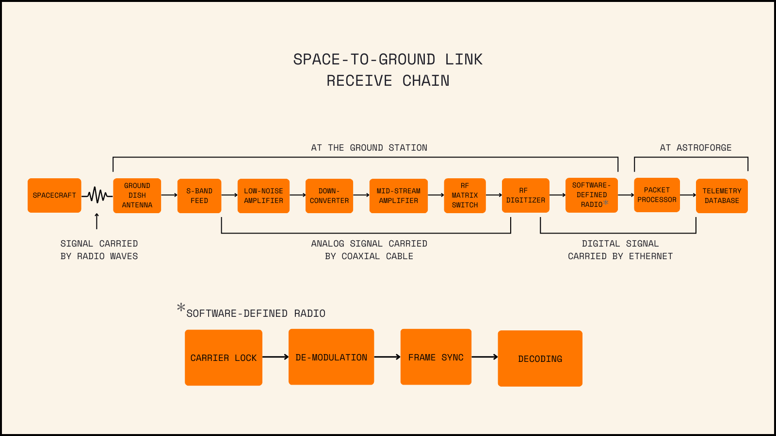
The receive chain at the ground station begins with an antenna receiving radio waves, which an antenna feed transfers to a coaxial cable. Each feed is tuned to a specific band and polarization, allowing one antenna to have multiple feeds. Some stations may use a down-converter to shift the S-Band frequency to an intermediate frequency (IF), which we’ll discuss more below.
There are many other variations to the above diagram. For example, the signal may pass through the matrix switch multiple times and the mid-stream amplifier(s) might be positioned before or after the switch or down-converter, etc. The matrix switch functions as an RF signal router, requiring proper configuration to connect the right feed to the right radio (or digitizer) - essential because ground stations typically have multiple of each component.
The Software-Defined Radio (SDR) requires specific configuration to extract data from the RF stream. This process involves finding and locking onto the carrier, demodulating symbols from the carrier or subcarrier, synchronizing to data frames, and decoding (or un-doing the forward error correction). Check out our previous lesson on RF for more details on symbols and encoding.
This full downlink (and uplink) chain must be verified at each ground station in order to ensure system compatibility. During ground station compatibility testing, we confirm that our systems can communicate with the ground station equipment. There are multiple ways to do this with varying levels of confidence. We primarily use integrated loop-back testing, where we send a known signal from our Mission Operations Center (MOC) to the ground station, which then processes it through much of the downlink chain before returning it to the MOC. Loop-back testing can be either short (signal turned around before reaching the antenna) or long (turned around at the antenna). This approach tests the full terrestrial networks and helps validate software systems and configurations, though it doesn’t account for potential mismatches with the spacecraft radio or antennas.
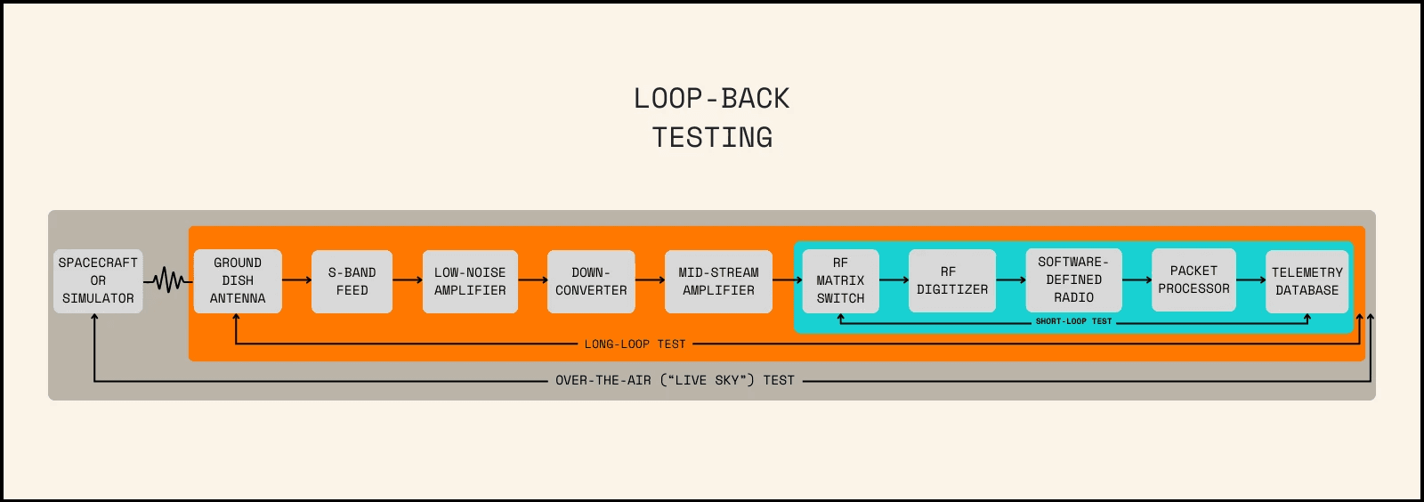
The highest fidelity test we can perform involves direct communication between the spacecraft and the ground station. However, this often poses significant risk to the spacecraft due to travel requirements. In lieu of the actual spacecraft, we designed a spacecraft simulator with the intent of replicating the Flight Software (FSW) and communications stack. This simple set up involves a computer running the latest FSW, an engineering model of the spacecraft radio, and an engineering model of the spacecraft antenna. This allows us to conduct tests as close to flight-like as possible without risking flight components. This test follows a sequence similar to the loop-back test, but the ground antenna communicates over the air directly with the spacecraft simulator, and telemetry responses are triggered by commands from the MOC. In preparation for Odin, we conducted over-the-air tests with the spacecraft simulator at two ground sites.
We also perform live sky tests, using actual spacecraft in orbit to verify other components of the ground system. While these tests cannot verify certain radio settings (as they aren’t listening to our spacecraft), they can verify mid-stream amplifier gain and polarization - parameters that are otherwise difficult to validate. We didn’t conduct these tests until Odin was in flight, but we plan to implement them much earlier in preparation for DeepSpace-2.
We also built a mobile test rack that containing RF ground equipment that allowed us to test our spacecraft anywhere in the world. This setup used the same ground SDR and software stack as our ground stations, enabling us to validate the spacecraft’s actual RF systems. This “mobile ground station” proved especially valuable for testing RF performance under different thermal environments during our TVAC campaigns.
What Worked and What Didn’t
We continuously tested the ground network, software stack, and RF chain in our lab. This rigorous testing allowed us to validate the full chain, verify updates, and develop a spacecraft simulator for realistic ground station testing. Additionally, our ground rack enabled us to test the full RF chain against the flight vehicle at our office, environmental test sites, and launch site.
For simplicity, we integrated just one ground radio model - the Kratos Quantum Radio connected to a SpectralNet Narrowband digitizer. This decision to use a single radio type significantly reduced integration and testing time, helping us prepare Odin for flight at record speed. This exemplifies our strategic choice of simplicity over performance optimization to compress testing schedules.
Odin’s test schedule was highly accelerated. Although we conducted short and long loop tests at nearly every station, we couldn't bring the spacecraft simulator to all ground stations to achieve higher confidence levels. We only managed to test with the simulator at two sites, Morehead and Mingenew, as well as at a KSAT development lab in Colorado. This limitation stemmed from travel and visa restrictions, along with regulatory challenges of transporting specialized equipment internationally. Some ground stations (I.e. Hartebeesthoek, Bangalore) either used their own equipment or worked with our engineers remotely for installation, meaning we never actually set foot on these sites. The lack of direct interaction with the sites and their engineers created ambiguities in system configurations, particularly complicating test communications at the Bangalore site.

We also conducted less testing on infrastructure using a 70 MHz intermediate frequency. This signal conversion, often referred to as an intermediate frequency, is used in some RF systems to simplify equipment downstream of a converter. While this abstraction allows ground station providers to support more frequencies with less equipment, it meant we received signals in the 70 MHz range, rather than the actual 2.1 GHz communication frequency. This discrepancy led to unfamiliarity with the signals and questions about whether we were sending/receiving at the proper frequencies, as the conversion component remained opaque to us as users. In addition, having both uplink and downlink at the same frequency at the radio created isolation issues when attempting to receive very weak downlink signals. Though we eventually resolved these issues, they consumed valuable debugging time during flight.]
The Issues with Odin
Here is the hard truth about the Odin mission: multiple ground station failures severely hurt our capabilities, limited our troubleshooting ability, and possibly even ended our mission. While we could blame others, the responsibility falls on us - we should have secured backup stations, particularly during the critical early mission phase.
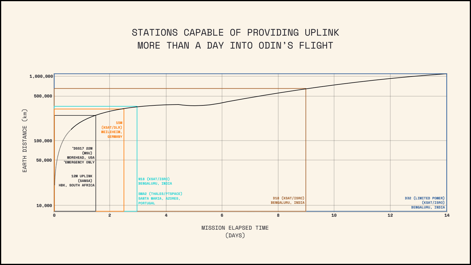
We knew we were taking a lot of risks, but we could and should have prioritized our efforts differently. For example, we knew that if Odin entered a tumbling state or safe mode after the third day, few antennas could reliably transmit commands to the spacecraft. This strategy, however, incorrectly assumed ground antenna availability - an assumption that proved fatal.
We originally planned around having double antenna coverage during spacecraft separation from the rocket, but discovered late in pre-launch planning that one of our key ground stations was already booked for this time slot. We should have prioritized securing a second ground station for that critical first stage of flight, even if it meant last-minute arrangements. It’s inexcusable that we relied on just a single ground station during those crucial first 4 hours when the spacecraft operated on battery power. Despite our confidence in our testing and preparations, the system failed.
Azores, Portugal
Santa Maria, a small island in the Azores, hosted one of our most valuable assets - a 15-meter dish with extensive availability that could track signals down to the horizon, if needed. This dish would have provided sufficient link margin for the first few weeks of the mission. We decided to add this dish when testing revealed issues on another dish, requiring us to dispatch an engineer to the island to integrate and test our system with Thales, who operate the site. This happened mere days before launch.
The results were impressive - the dish performed even better than our projections indicated. A However, less than a day before the launch, a critical part of the uplink chain - the Power Amplifier - burned out. Normally, these dishes maintain backup components that allow for recovery within 24 hours of a failure.
Unfortunately, the team at the dish had recently used their backup components, leaving no spares available. This threw us into a scramble. One of our contractors located a power amplifier in Italy, but even with a private flight, we couldn't get it installed and tested until several days into the Odin mission. The unfortunate reality was that this station never became fully operational during the mission.
Australia
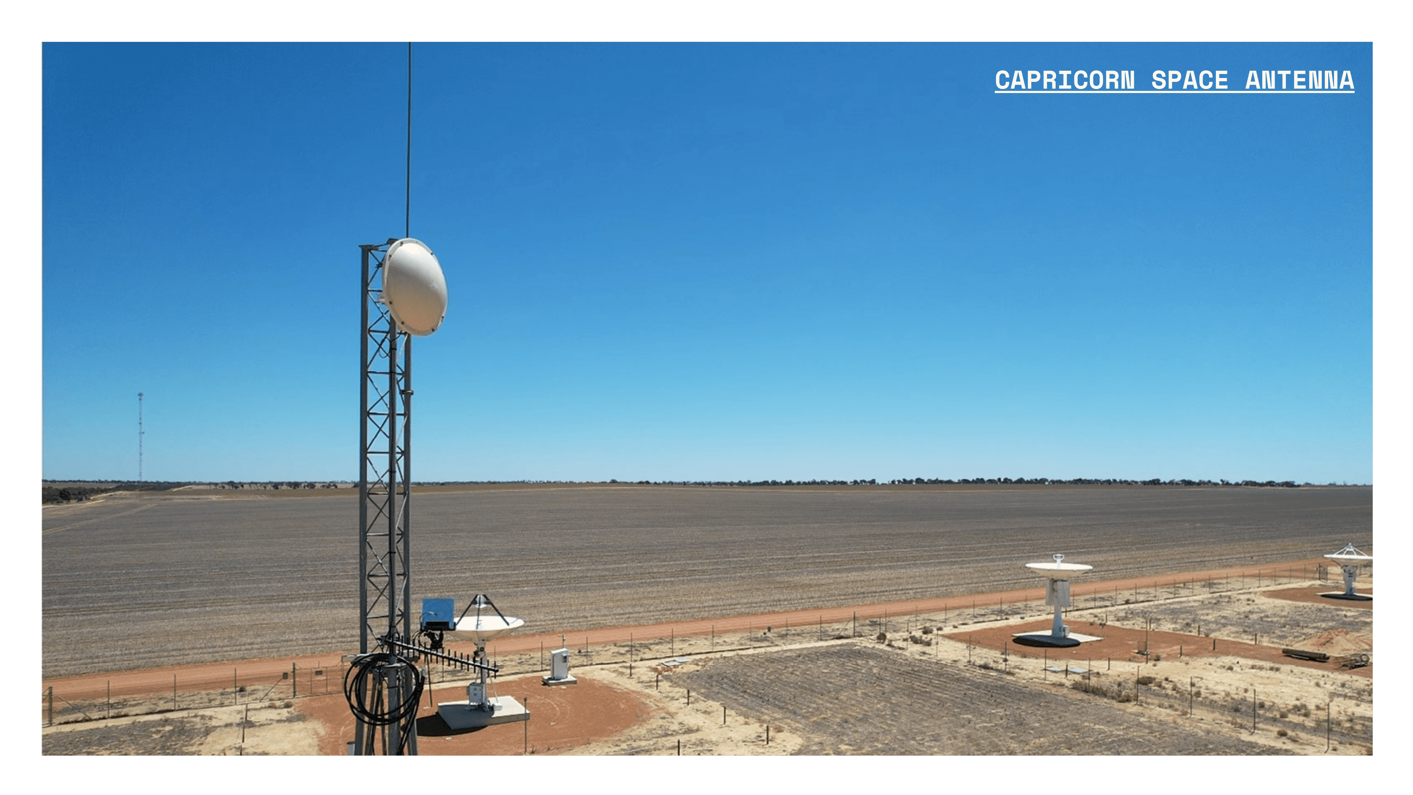
For the first 8 hours of the mission, we planned to communicate with Odin via a 5-meter diameter dish in Australia. Since a smaller dish was sufficient immediately after Odin's separation from the Falcon 9, we partnered with Capricorn, a company we had previously worked with successfully.
Capricorn was great—they welcomed us with open arms to conduct our onsite testing. We meticulously checked and double-checked all of our configurations to ensure everything would function perfectly. Then came launch day.
On launch day, things went awry. Analysis of the data later revealed that for at least the first 45 minutes of flight, incorrect configuration settings prevented any communication with the spacecraft. We also couldn’t verify correct polarization, which - if misaligned - would have prevented our link budget from closing on this pass. The sobering reality is that Odin may have been attempting to communicate with us had we managed to send a command through in those critical first couple of hours, but we simply weren't listening.
India
India hosts one of the world’s best dish complexes. In fact, most missions on our rocket had contracted with the India team. The Bangalore complex features three major dishes we planned to use: two 18-meter dishes and one 32-meter dish. However, as we’ll explain shortly, only one of those dishes was both effective and available during the first two days of our flight.
We accessed these Indian dishes through KSAT, who diligently facilitated testing both at their Denver lab and with the India site. Since several other missions also required the 32-meter dish, we were limited to the 18-meter dishes for the first few days.
About two weeks before launch, during long-loop testing, we detected unusually high interference levels on one of the 18-meter dishes. The noise levels were so high that we couldn’t complete our test. Despite checking everything from our equipment to the dish hardware, we couldn't identify the problem. Interestingly, the same interference pattern was barely detectable when testing on the 32-meter dish.
We eventually discovered that a new cell phone tower had been installed adjacent to the 18-meter dish - an oversight that seems almost unbelievable. This interference affected everyone operating in the same frequency band and essentially rendered the dish non-operational for Odin. The local government in Bengaluru and the Indian Space Research Organization (ISRO) offered assistance by experimenting with powering down the cell tower or reducing its output, which tests confirmed would eliminate the noise. Ultimately, they managed this for a couple Odin passes, even on the other dishes, but could not guarantee this in advance, preventing us from relying on the most affected antenna during our flight.
As a result, we had access to only one 18-meter dish for the first two days, with the 32-meter dish becoming available later. On the second day of the flight, Intuitive Machines graciously relinquished one of their time slots for our use. Before utilizing the dish, we performed a loop-back test as described above to verify our ability to send and receive spacecraft signals.
Unfortunately, this loop-back test got stuck. We couldn't turn it off. Despite the best efforts of everyone at the ISRO-operated dish, the entire pass was rendered invalid. Even if our spacecraft was transmitting back to Earth, the power from the transmitter was so strong it would have completely drowned out the signal.
United States
Our ground station in Morehead, Kentucky can only receive signals from Odin and DeepSpace-2 - not because of technical or equipment limitations, but licensing restrictions. US regulations reserve the entire deep space S-band for NASA’s Goldstone, California site. This applies despite Morehead being nearly 2,000 miles away and our willingness to coordinate transmission times with NASA (something we have to do anyway). It’s also ironic that our spacecraft can legally transmit within Goldstone’s view, under our FCC license. As AstroForge pioneers new territory, we’re identifying outdated regulations and working with stakeholders to address these issues.
The Morehead site encountered another issue during Odin’s flight. Despite conducting thorough RF compatibility testing on-site, we neglected to perform a live-sky test at Morehead before flight, an oversight that proved costly. Our RF digitizer required an additional mid-stream amplifier in the receive chain to provide stronger signal amplification than other radios at the site (including a DSN radio). We haven’t determined whether this requirement is specific to our unit or applies to all radios of this model. Unfortunately, we only discovered this issue several days into Odin’s flight while conducting a live-sky test tracking Intuitive Machines’ lander signals.
Where We Got Lucky
Before launch, we underestimated the incredible support of the space community. Approximately 7 hours into the flight, we received a message that amateur radio enthusiasts had detected Odin’s signal. AMSAT-DL (the German branch of the Radio Amateur Satellite Corporation) had been tracking Odin and other spacecraft from our launch. Despite the “amateur” label, AMSAT-DL is an education-focused organization operating highly sensitive and sophisticated radio equipment. They recorded Odin’s first signal and confirmed a second one.
Beyond the radio community, optical observatories also searched for Odin and the other spacecraft from our launch - notably, all except Intuitive Machines entered anomalous state within a day of separation. We received valuable assistance from Pine Park Observatory, University of Arizona, and Project Pluto, who dedicated telescopes and data processing resources to our mission. We deeply appreciate their extensive efforts.
Improvements Going Forward
Many of the issues we faced with Odin stemmed from ambiguities in either our systems or the systems of our partners. We can address these problems by implementing a more standardized and robust approach to RF compatibility testing for DeepSpace-2. After analyzing our assumptions for Odin, we’ve made several key improvements.
Design-To Link Budget
When discussing a vehicle’s RF performance, we need to specify exactly which situation we’re addressing. With Odin, we typically focused on the max-performance case, but for DeepSpace-2, we’ve established a very specific set of criteria. Our link is designed and discussed in the context of:
Max design range:
20,000,000 km
Bit error rate of 1 in 100,000 (1e-5)
Safe mode operation:
5 dB pointing loss (i.e. antennas not pointed directly at Earth)
Minimum operational data rate: 100 bps
2nd-best performing ground station:
This ensures we aren’t overly dependent on a single station
Simply standardizing these parameters improves our internal communication and planning. Building our baseline around single fault tolerance in the ground system makes us inherently more robust.
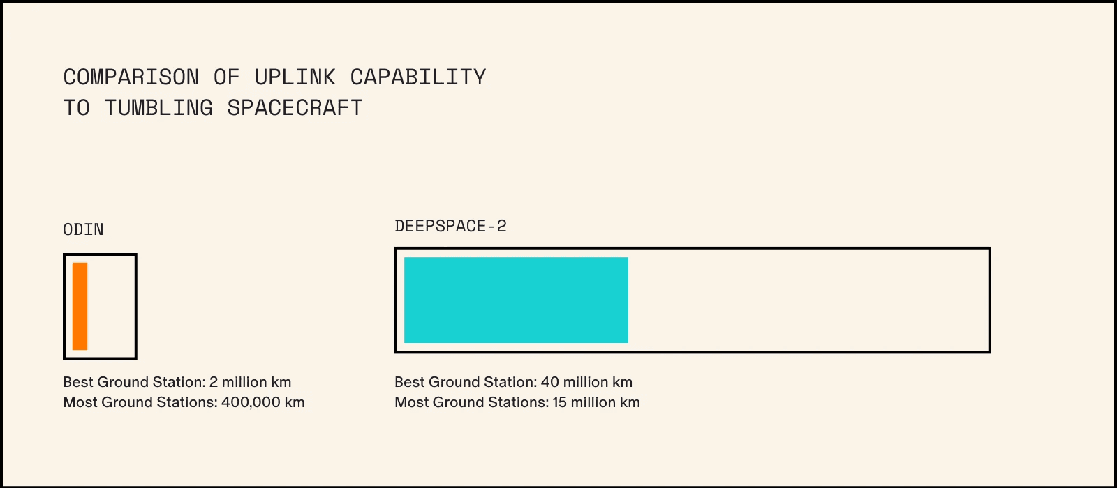
DeepSpace-2 features significantly higher performance links, giving us options for additional antennas. To illustrate this improvement: every ground station used for Odin (except Mingenew) can confidently send commands to DeepSpace-2 at distances up to 15,000,000 km - compared to Odin, where only our highest-power station could reach 2,000,000 km. These smaller antennas also benefit from wider beam widths, requiring less precise pointing.
Ground Pass Automation
Each scheduled communication opportunity with a spacecraft is known as a “pass” or “contact.” For Odin, we managed these passes manually and ad-hoc due to our limited development time and the deep-space industry’s traditional reliance on lengthy, manual processes. Each pass required planning, scheduling, execution, and post-contact analysis.
With DeepSpace-2, we’re implementing automation, not because it’s faster, but so that we can test each process component and ultimately free up our operators and engineers to focus on troubleshooting issues. This automation will handle routine pass mechanics such as radio configuration verification, antenna pointing, navigation measurements, and RF recording. We can test these automations on our Hardware-In-The-Loop (HITL) radios and during integrated tests with ground stations.
For DeepSpace-2, we’ve established an internal single source of truth for ground station data, including pass schedules. This ensures all mission planning and operations tools access the same information, reducing the risk of a mismatch between planning and operations. For example, we can verify that our ground antennas are pointed exactly where our trajectory planning tools say they should be.
While developing this system requires a lot of effort from our small team, the ability to test and refine our processes well before launch significantly reduces communication risks on the ground station side.
Testing, Testing, Testing
We’re further reducing risk through more extensive and targeted testing. For Odin, AstroForge visited two ground sites and one RF lab to test with real hardware — an impressive effort given our timeline. These tests primarily focused on end-to-end integration and, when possible, over-the-air testing.
For DeepSpace-2, we’re better prepared for testing, with necessary software and procedures already in place from our Odin experience. We are already conducting extensive radio testing at our facility using both flight and ground radios. Soon, we’ll begin RF compatibility tests with DeepSpace-2 ground stations. These will include live-sky tests in addition to the short-loop and long-loop tests done for Odin, allowing us to validate more parts of the receive chain. We’re also planning RF compatibility testing at more of our our ground stations.
The pass automation we are producing also includes radio configuration storage, versioning, and validation. A key part of the RF compatibility testing will be ensuring both we and our ground station partner have the correct radio configuration settings.
Antenna Selection
The DeepSpace-2 ground network largely builds on our experience with Odin. While we acknowledge the shortcomings we faced with Odin, we recognize that this is a learning process for everyone involved. All our ground station providers for Odin were knowledgeable, helpful, and professional. We aim to continue these partnerships and grow alongside the developing industry as much as possible.
We plan to add several more ground stations for DeepSpace-2, driven by two primary requirements:
Continuous coverage for the first 24 hours, filling the Pacific Ocean gap we experienced with Odin
Double coverage at spacecraft separation and for as much of that first 24 hours as possible
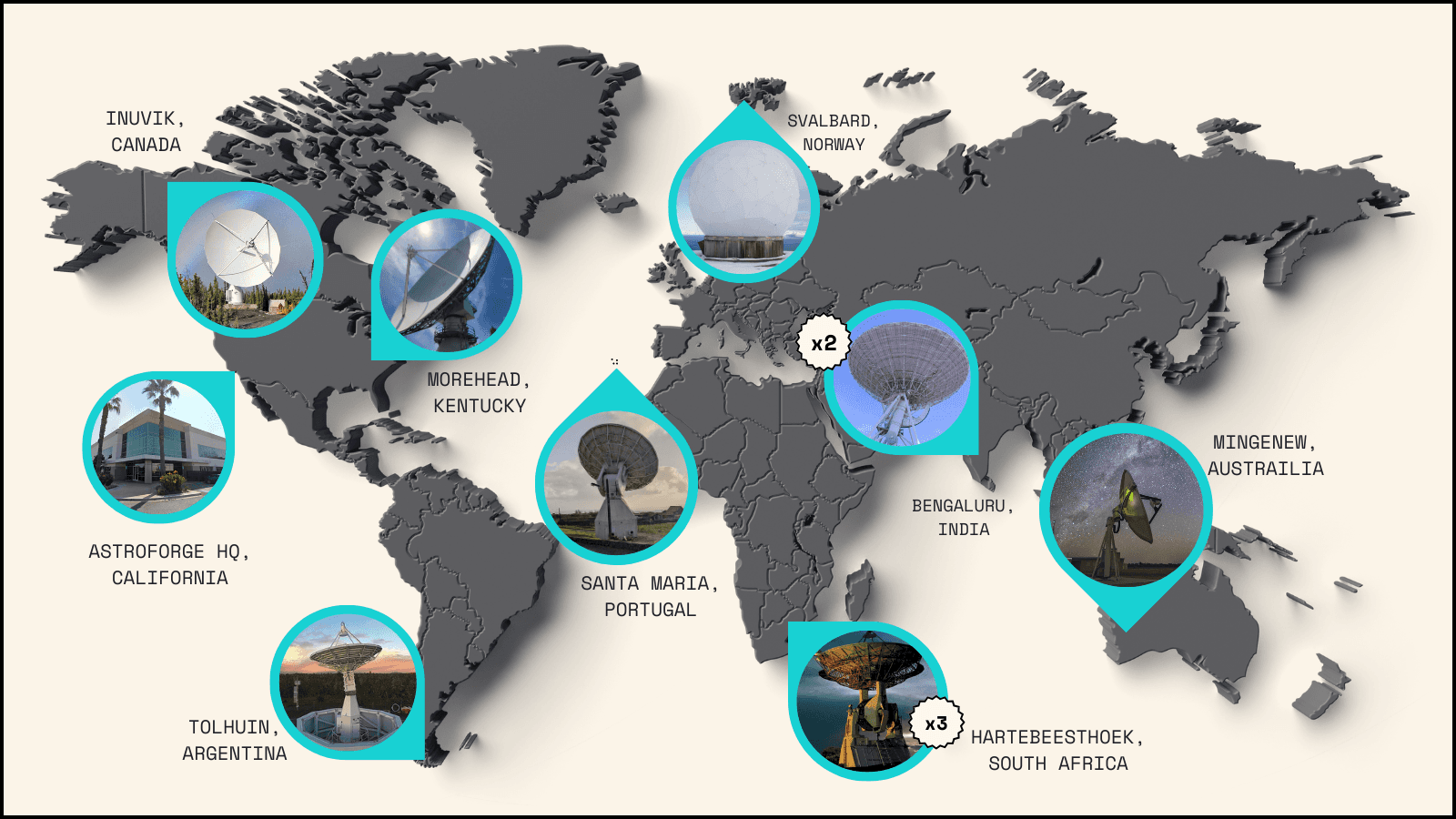
We can meet these requirements using smaller antennas for two reasons: DeepSpace-2 will still be relatively close to Earth, and it has a more capable RF system than Odin. Below is a map of the primary antennas we are currently considering for DeepSpace-2. We’ll also integrate additional smaller backup and contingency antennas to help cover the first 24 hours of flight. This setup is subject to change as we continue working with multiple ground station providers for DeepSpace-2 and future missions.
You’ll notice we’re only adding one more antenna than we used for Odin, though at two additional locations. This limited expansion stems partly from the scarcity of sufficiently large antennas, but primarily from our testing constraints. With finite time and resources before DeepSpace-2's launch, we need to focus our testing efforts on fewer key stations.
Having learned some hard lessons from Odin and equipped with a more capable spacecraft, AstroForge is moving forward with a robust ground architecture for DeepSpace-2. We are developing and deploying integrated testing and automation systems to mitigate many key ground infrastructure risks. While challenges specific to deep space operations and the nascent commercial infrastructure remain, we’ve always anticipated these obstacles. We believe these remaining risks are worth taking to achieve our mission of mining asteroids.