Spacecraft Solar Array Structures
Matt Gialich
Spacecraft Solar Array Structures
Solar arrays are critical components of spacecraft power systems, providing the energy needed for propulsion, communications, and mission operations. This post explores the structural considerations, design requirements, and engineering challenges involved in creating solar arrays for spacecraft. From the foundational principles that guide design decisions to specific case studies of our Odin and DeepSpace-2 spacecraft, we'll examine how solar arrays must balance competing demands of power generation, structural integrity, mass limitations, and deployment reliability. Understanding these complex trade-offs is essential for developing solar array systems that can withstand the harsh conditions of launch and space environments while delivering the power needed for successful mission operations.
Solar Arrays
The solar arrays are a vital part of the vehicle’s longevity and therefore need to be designed to last in the harsh external environment of space. This means they must be built for radiation, extreme thermal cycling, and at the same time stay extremely light. To do this, we must first constrain our design. Some key constraints include, fitting within the allotted volume provided by SpaceX, providing enough power to stay functional even with failed deployment, and survive launch loading.
Odin
Before we get into the details of DeepSpace-2's design, it’s important to note that we ordered off the shelf solar arrays for Odin from Pumpkin Space Systems. This meant that all we were responsible for was testing, and dictated power requirements, but the structural design was done completely out of house. These arrays structurally were modules laid onto a PCB backing. This lead to a resulting efficiency of 53 W/kg for these arrays, which is something we wanted to get more efficient on for the next model.
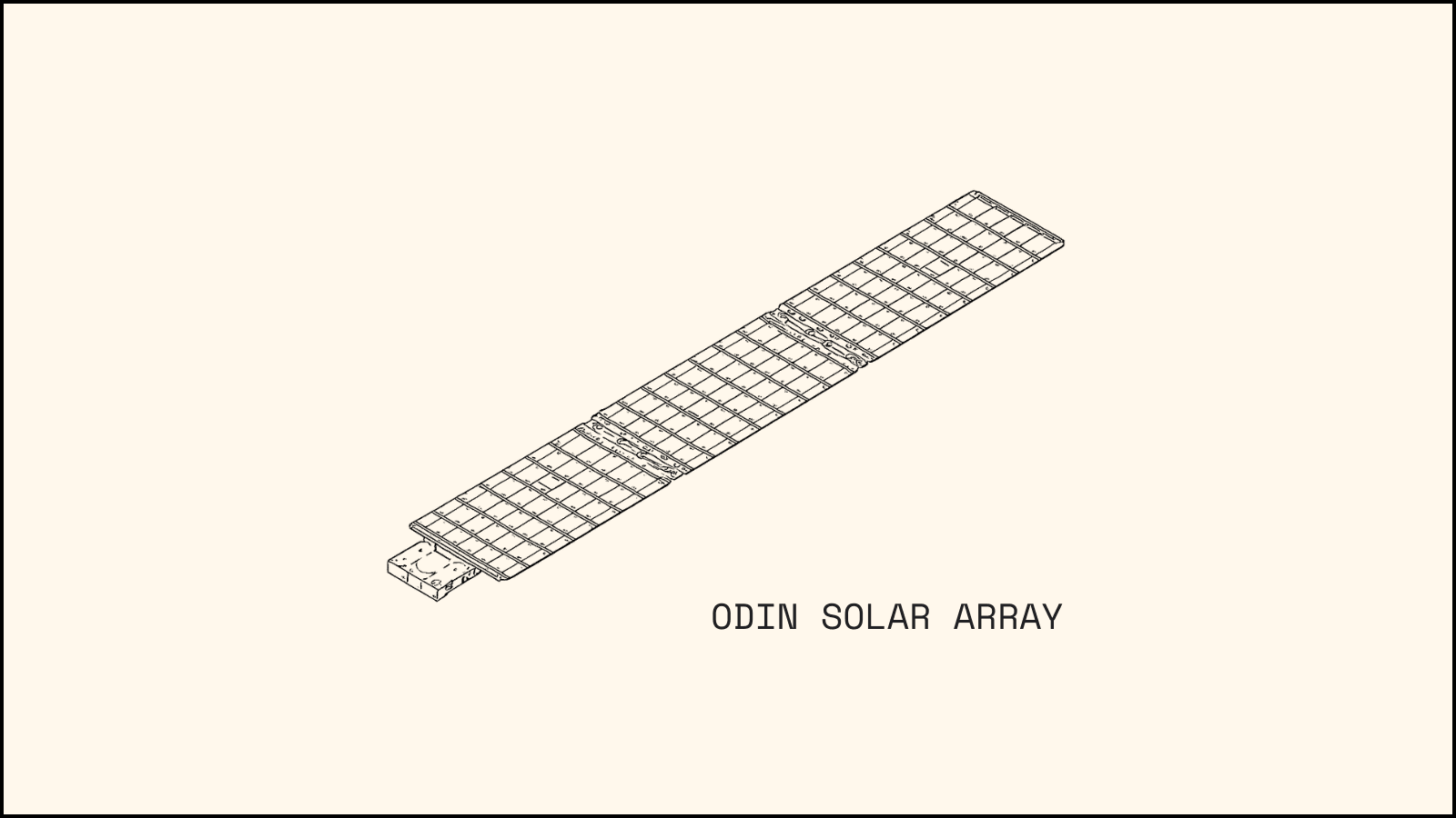
All arrays need to be stowed when launching to comply with SpaceX RPUG. Our hold down release mechanism (HDRM), through vibrational testing turned out to be quite the problem for us. We had several accidental deployments when running through random vibe testing, where we run a extended duration test running through all frequencies and amplitudes the spacecraft should see during launch. The solution ended up being to remove a spring that was causing the preload to exceed our HDRM specs. Once removed, we passed all further testing, however, we learned to test as early as possible from this.
Solar Array Requirements
What are the requirements of a mission that drive array design? While the following list is not exhaustive, it includes some key questions that should be documented to ensure the engineering team understands the design requirements:
What is the overall power that needs to be generated by the solar arrays?
Does the array need to actuate on orbit?
What are the maximum expected loads/forces that the solar array will experience?
What temperature extremes will the solar array be subjected to (coldest and hottest cases)?
What size limitations exist for the spacecraft? I.e., is there a defined volume that the spacecraft must stay within during launch to avoid intruding on other payloads?
How will the array connect to the main structure of the spacecraft?
What mechanism will be used to deploy the array?
Establishing a detailed, well-documented understanding of mission and array requirements as early as possible helps set a team up for success.
Applying the Above to DeepSpace-2
DeepSpace-2 is launching to space in what’s known as a ride share program. This means we aren’t buying a rocket launch dedicated to DeepSpace-2. Instead, Intuitive Machines (IM) has purchased a rocket launch from SpaceX to travel to the moon, and we’re essentially hitching a ride by purchasing a ticket from IM. We have purchased a 200kg mass budget from IM. Though the SpaceX Falcon 9 could potentially carry more, we are contractually limited to 200kg. Exceeding this limit would disqualify us from the mission.
With this information and our mission requirements for spacecraft performance upon orbit, we can answer many of the questions listed above using SpaceX’s Rideshare Payload User’s Guide (RPUG):
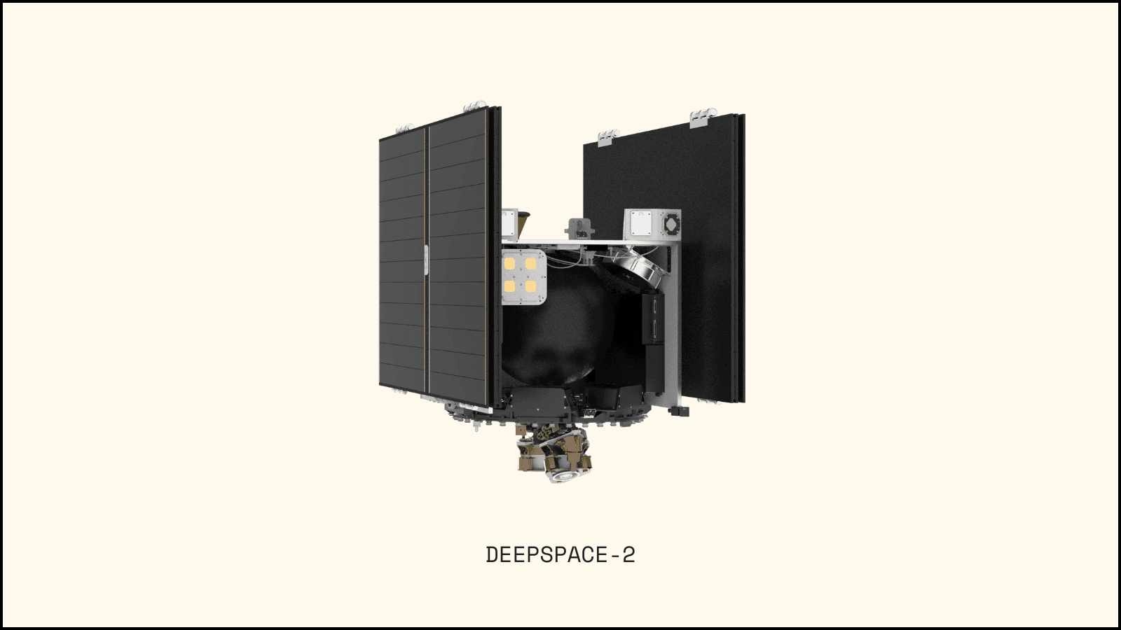
For DeepSpace-2, we rough sized a spacecraft mission that resulted in electric thrusters from Safran, which allowed us to then size the overall power requirement at 1kW per wing. This means that we need to generate at least 2kW of power to ensure we can maintain propulsion to reach our targeted asteroid. We then added on power inefficiencies to determine a required panel size. We then sized the panels such that one wing will power one thruster at reduced power.
Our solar array does need to actuate, and therefore each wing has a motor located at the base of the wing
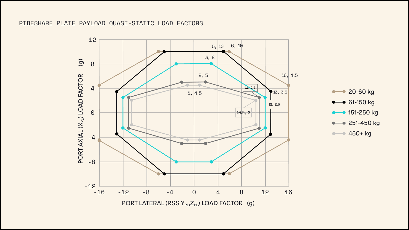
As mentioned in the previous post on Spacecraft Structural Design, our vehicle mass is 200kg. Per table 6-4 and the graph below, the Quasi-Static Load Factors for a 200kg payload are 8.0g (where g = Gravity) for axial loads and 12.5g for lateral loads, respectively. This load is applied to the spacecraft design in a Finite Element Model, and we ensure the hardware that connects the wing to the spacecraft is sufficiently sized to survive these load factors.
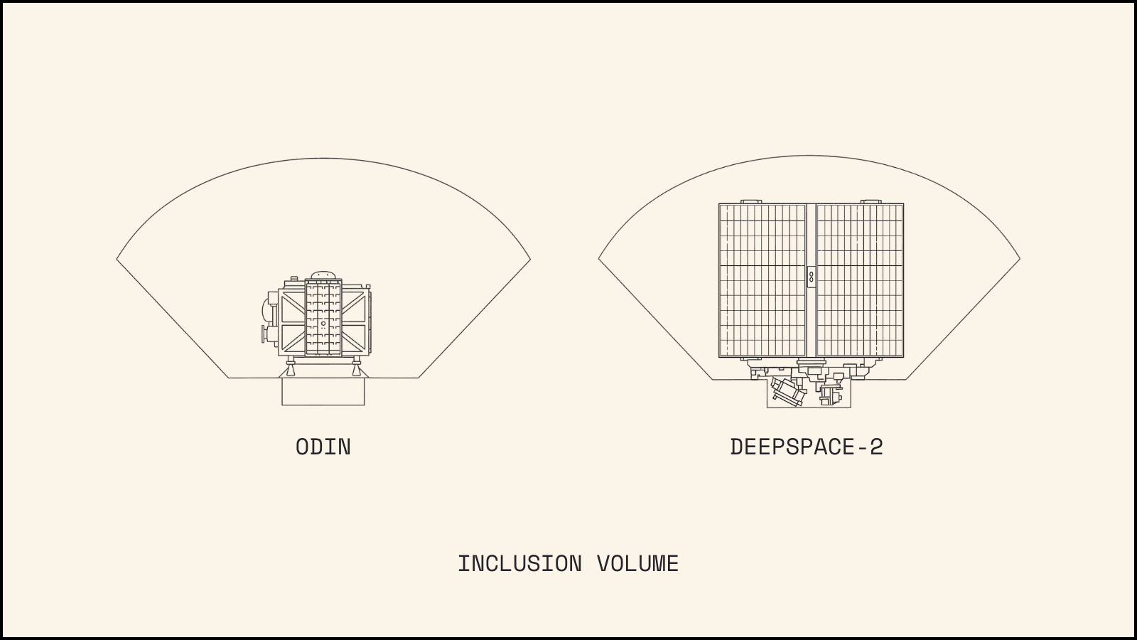
Furthermore, knowing our maximum allowable mass of 200kg and our specific launch vehicle - a SpaceX Falcon 9 rideshare with an XL Plate with Internal Inclusion - provides critical structural parameters. This information defines both the inclusion volume our spacecraft must maintain during launch and the interface geometry between our spacecraft and the launch vehicle. These easily obtained specifications provide valuable guidance for mission design and structural requirements.
DeepSpace-2 Solar Array Design
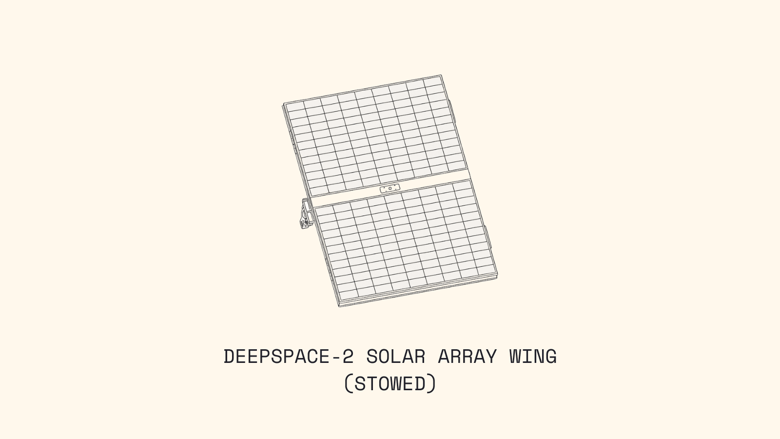
When we started the solar array design for DeepSpace-2, we went with a flexible module to save mass and allow ourselves to try something new with the structure of what our arrays would look like. As an initial concept, we wanted to make a “picture frame” out of carbon fiber rods, and cure a thin carbon fiber substrate across, leading to what effectively looked like a canvas stretched across a frame. We wanted as much power in as possible in the case of a failed deployment, so we went with a bifold design. Taking the lessons learned from Odin, we built the frame and canvas and immediately sent this into vibrational testing to collect data. We were able to push this design beyond the launch loading envelope before it failed, however this did prove the failure point was a peel failure in the bond line. To correct this, we needed to add additional fender washers in these areas to better support the substrate and reduce the load and therefore the likelihood of a peel failure. This, however, added mass and as we fleshed out the design more with stiffeners, the structure was becoming quite heavy.
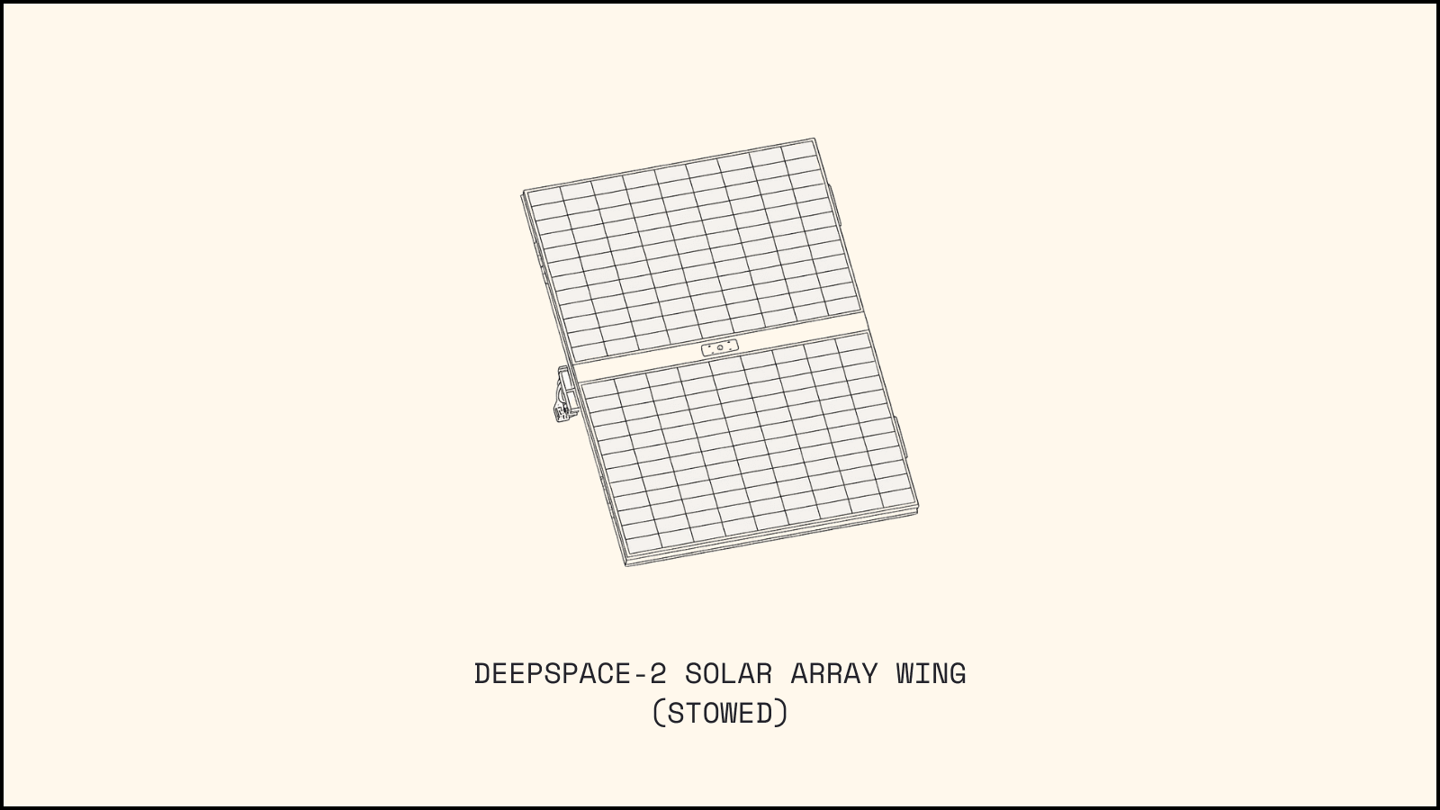
At this point, we had proven an initial concept, but it was time to return to the basics. Did we fit into design constraints and were we truly more mass efficient with this method? The answer to both proved to be no. As it turned out, we didn’t fit into the launch volume as a bifold array, and the stiffening required to secure the substrate to the frame did not scale well relative to the industry-typical sandwich panel design.
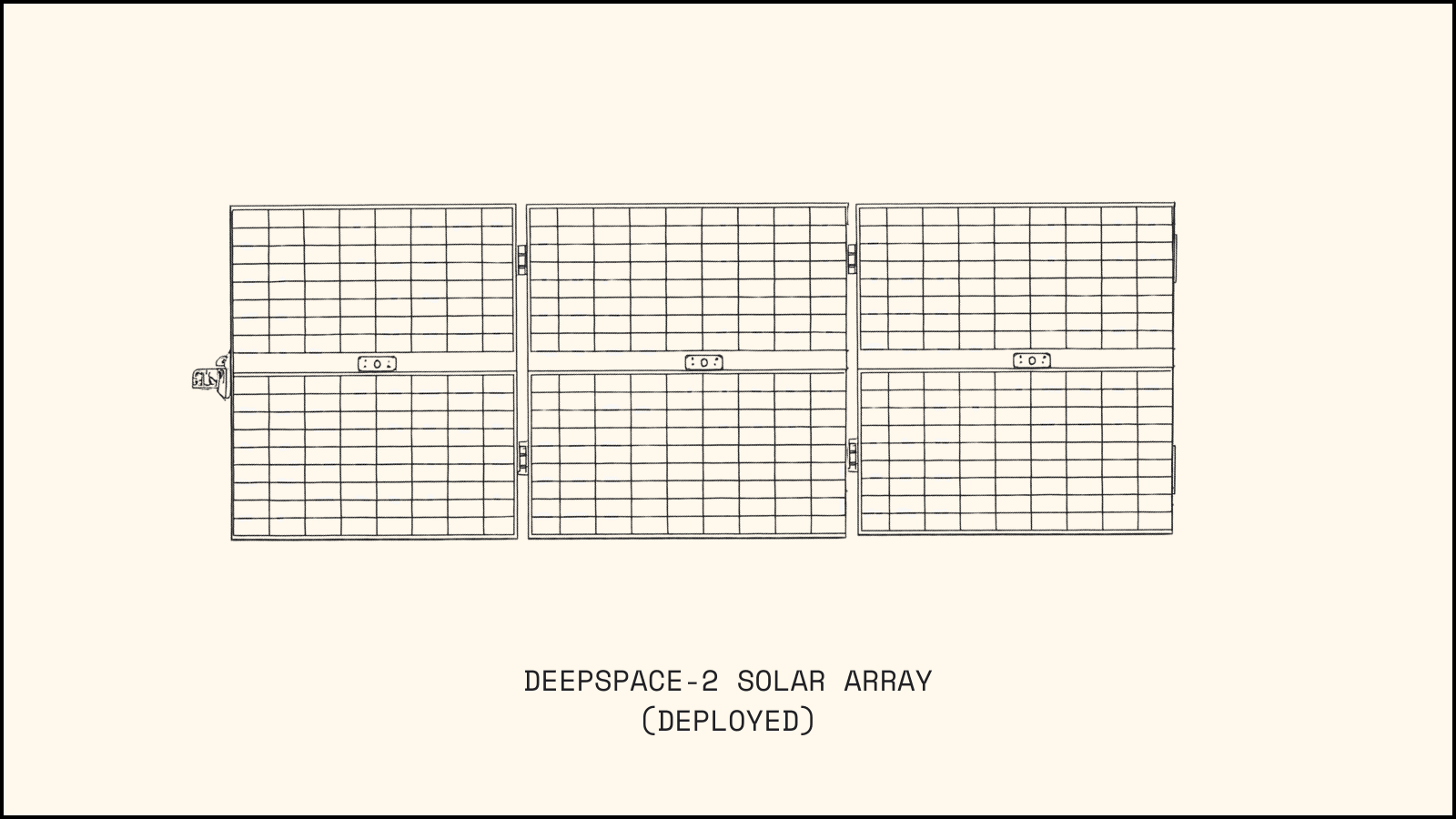
Due to this, we had to turn toward a sandwich panel and three panels per wing as shown below. This design increases risk of producing less power should the arrays not deploy successfully. However it allowed us to increase the total number of modules on the arrays, which therefore increases our ability to produce power and increases the margin in our power budget.
Understanding Major Bill of Material Line Items
Before progressing too far with vehicle design, you must identify the required solar array components. While this seems obvious, components are rarely fully defined and selected before significant structural design work must begin.
For DeepSpace-2, we require a substrate/structure, solar modules, an articulating mechanism/motor mount, hinges, bumpers, locking mechanisms, and hold down release mechanisms (HDRM). Of these, all but the solar modules and the HDRM will be designed in house. We will dive deeper into these components below, but first we will walk through a refresher on the importance of the difference between strength and stiffness. Understanding this relationship plays a crucial role in the sizing of the array components to survive launch and successfully deploy when performing the mission.
Solar Array Primary Structure Decisions
Now that we have addressed the driving requirements and load cases for the solar array design, let’s take a look at some other primary structural components. The main elements of the primary structure are:
Solar Array Panels
Motor Mount
Hold Down Release Mechanisms (HDRMs)
Panel Hinges
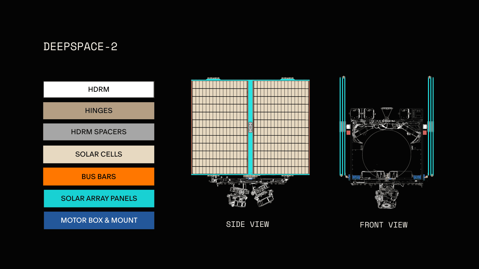
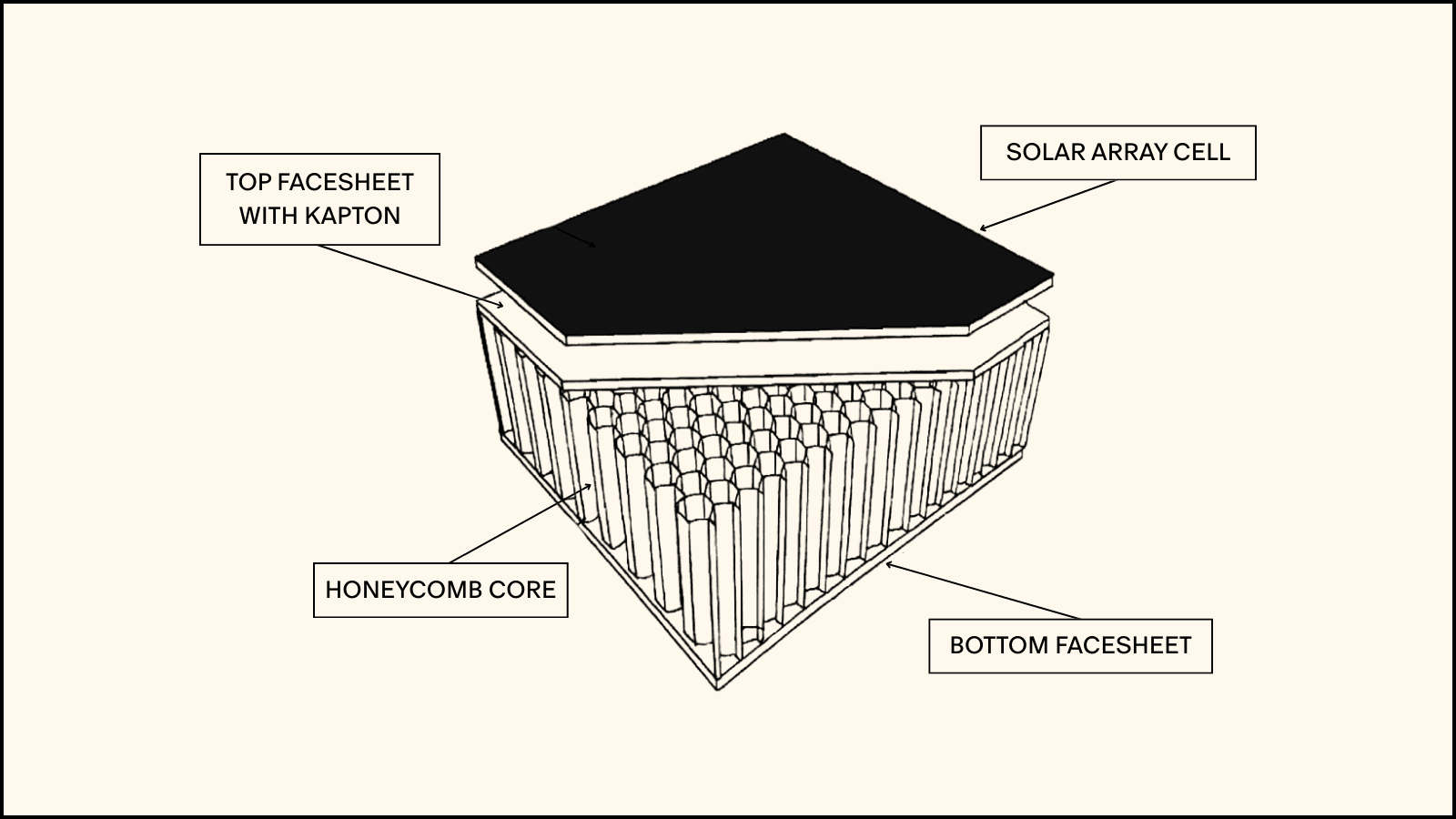
DeepSpace-2's solar array panels are sized to optimize power generation. A basic rule of thumb is: the more power the spacecraft needs, the larger the array area. To optimize area and minimize overall weight, the panels are constructed with carbon composite honeycomb core sandwich panels. The composition of these panels is similar to the radiator panels described in the first Structures blog post, but with carbon composite face sheets to help reduce the overall mass.
The side of the panel that the solar cells are bonded to is also coated in Kapton to provide a layer of insulation and prevent short circuits between the power-generating cells and the composite substrate. One of the complexities of using an electric propulsion system is that we create a field of plasma surrounding the spacecraft. This creates an electrical pathway to all external components of the vehicle. With the panels being carbon fiber, there are small imperfections where microscopic fibers sticking up, creating an electron concentrator, which could cause our propulsion system to arc from the arrays. To prevent this, we will need to apply another coating to the radiating side of the arrays to seal these imperfections off.
As mentioned above, each solar array wing consists of 3 panels connected by hinges to allow the area needed to generate power for the spacecraft while also ensuring we conform to the SpaceX ride share inclusion volume. This means we need to ensure the solar arrays have a strong connection between the panels and also to the spacecraft bus, so let’s explore some of the hardware that helps accomplish this.
Solar Array Panel Structural Hardware
Each DeepSpace-2 solar array wing has a motor mount, two Hold Down and Release Mechanisms (HDRMs) and a series of panel to panel hinges. The motor mount and HDRMs ensure each wing has a strong structural connection to the spacecraft bus. The panel hinges connect each panel to its neighbor, and also allow the array to stow.
Motor Mount
The motor mount consists of a motor to articulate the arrays, a gearbox because the arrays are so large they have too much inertia for the motor to articulate on their own, both of which are mounted to the side panel together. This stack up creates a large and relatively massive cantilever, so they need a connection to the panels to stiffen the connection and prevent the gearbox pin from bending, as it is the thinnest structural connection to the panels, so we definitely do not want that to break.
Hold Down and Release Mechanisms (HDRMs)
The hold down release mechanism prevents the arrays from deploying in the launch vehicle. This is an extremely important part, because if there is an accidental deployment we could damage our arrays before we even get to space, and damage other spacecraft as well. It must hold the mass of the arrays as is a solved problem by many companies, and is not relatively expensive to go to a vendor for, as a result, we are acquiring this component from the vendor with the highest load rating and lowest mass.
Panel Hinges
The panel has multiple types of hinges, there is a root hinge, which connects the motor to the first panel, and the panel to panel hinges. Within these hinges is a hard stop, spring mechanism, and a samarium cobalt magnet to lock the hinges when they are fully deployed. The spring sizing is made to be the lightest they can be without deforming the arrays upon full deployment, as there is a lot of inertia that stops almost instantaneously with this passive deployment mechanism. The magnets are then sized to hold the arrays if the spacecraft were decelerated from a roll at the maximum rate we could desaturate at.
Structural Considerations
The solar arrays have a different driving set of structural considerations in comparison to the entire spacecraft. Some still carry over such as the fact that these arrays need to survive being launched. But this subsystem has a deployment mechanism that must hold steady through these launch loads and the impart a significant shock into the system when they deploy. These wings are a large cantilever into their attachment point. Under most of its operational life cycle it doesn’t see major forces and deflections, but on deployment it snaps open with such force from the HDRM and spring driven hinges that it must be confirmed that this shock doesn’t break the wings or the panel they are attached to. This is a critical deployment that imparts a lot of force into the craft through a relatively small connection. And you only get one shot at it so you have to make sure it is successful.
The launch and deployment are the largest operational forces we have to consider in determining whether these wings can withstand their loads. Most of the on-orbit operations will have extremely reduced load factors when compared to these two cases. That is not to say that they are not important but it is less critical to the survivability of the arrays.
Structural Simulation
So looking into how we want to model the solar array unit, there are several key considerations we need to evaluate. First we have two unique configurations of the solar array, a transitional stage, and operational considerations.
For both configurations the panels are have a set of hinges in between them. Each panel is constrained to each other through these hinges, limiting the available motion of the panel. The root panel is then connected to the body by the root hinge in both cases. This is a specific area of concern as that is where all the force contributed by the array goes through DeepSpace-2 in the deployed case. The stowed case has the addition of the HDRM attaching it to the spacecraft with a specific preloaded bolt. The breakdown of each of the modeling considerations are showcased in the table below.
In creating the mesh for the arrays we want an increased density of nodes at the hinge and HDRM attachment points to get as much detail as we can but for the larger expanse of the solar array a coarser mesh can be used.
Stowed | Deploying | Deployed | |
Analysis Type | Launch loads (static and modal) | Multi-body dynamics (nonlinear transient) | On-orbit dynamics (vibrational) |
Boundary Conditions | HDRM bolted to panel | Root hinge bolted to panel | Root hinge bolted to panel |
External Loads | Launch quasi-static and vibrational loads | Mechanism driven forces | Solar radiation pressure |
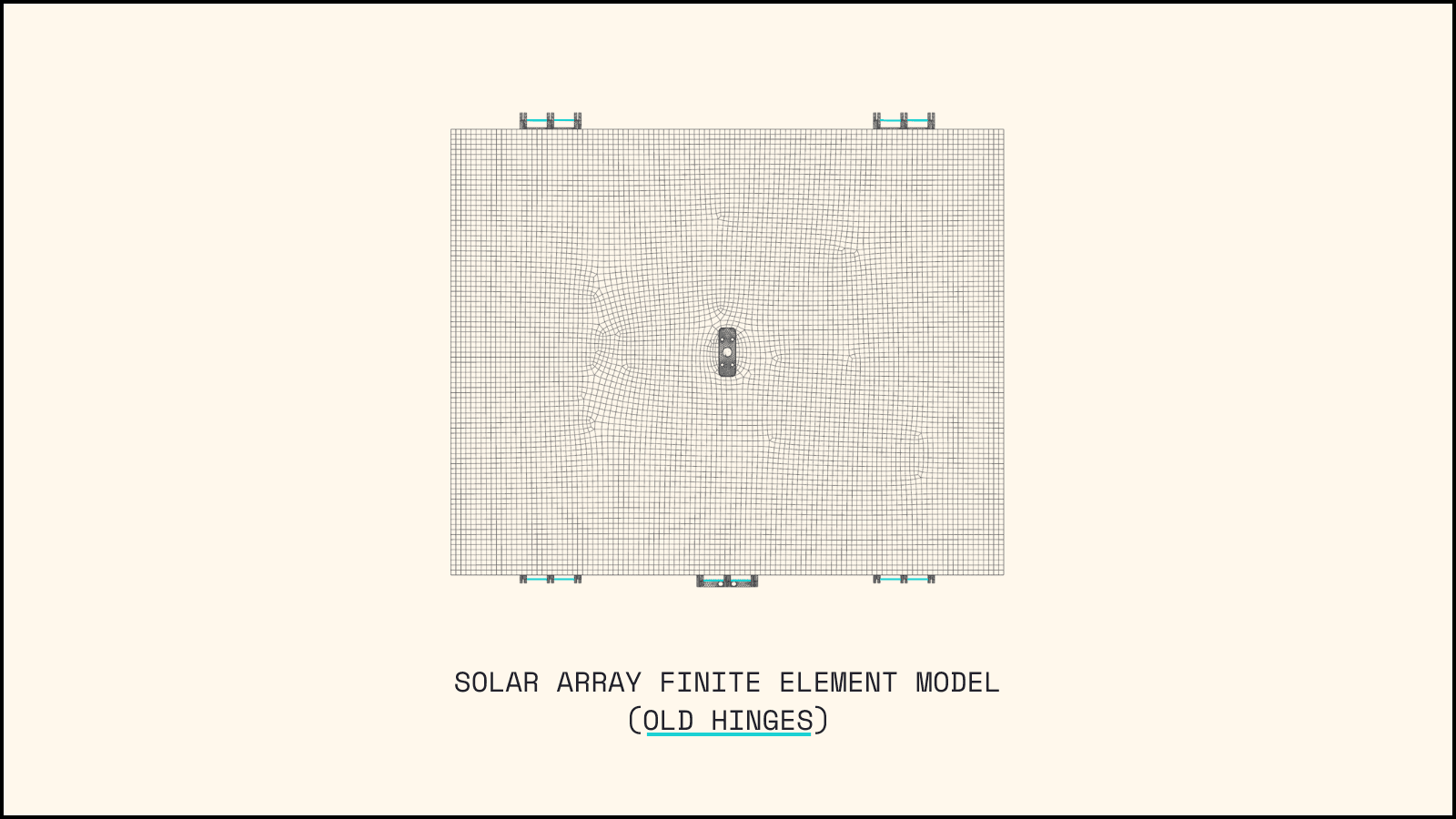
For each of these models there are steps to increase the fidelity and accuracy of the solar array. For example the first stowed array breakout model solution featured a root hinge connection and HDRM connection that were fixed. In reality, these locations are not fixed but instead move relative to the panel that they are attached to. So employing prescribed displacements at those points representative of how much the panels move under the quasi-static load is one step further of accuracy. Additional modeling factors present in this workup include bonded hinges to the panels, and hinges that have a bolt connection between them stacking up RBE2 and CBAR elements to mimic that hinge pin. Since this model, the hinge design has changed and the finite element model is being adapted to the new design as well.
In looking at the deployment case the most critical thing to focus on is the multi-body interaction. The behavior between each of the joints need to be successfully defined. For elements like hinges you need to properly constrain the degrees of freedom that do not correspond to rotation and for a higher degree of confidence model looking into the proper friction coefficients can also be important. The springs centered around the hinges are compressed when stowed and that stored rotational potential is activated when firing the HDRM. This spring stiffness must be included in the hinge behavior as well. By setting all these boundary conditions properly a model predicting, shock induced stress, deformation, deployment time, and settling time can be developed to inform any design changes or considerations.
For the on-orbit model the main consideration is vibrational response and overall deflection. With every course correction the spacecraft will perform, that will cause vibrations to occur in the spacecraft. These are mostly non-critical but for the solar arrays which exist on a very large cantilever, the oscillations could prove more detrimental so this behavior must be investigated. Additionally, the sun exerts solar radiation pressure over the surface of the spacecraft. The solar array wings are large flat surface areas that can pick up this pressure like a large sail exerting this force over a widespread area. Because of this, the solar array wings might distort slightly from this. This amount of deflection is not worrying from a structural health position but now the incident angle of light hitting the solar arrays is slightly different that the intended angle possibly leading to a variation in power generation. Therefore the amount of deflection needs to be known.
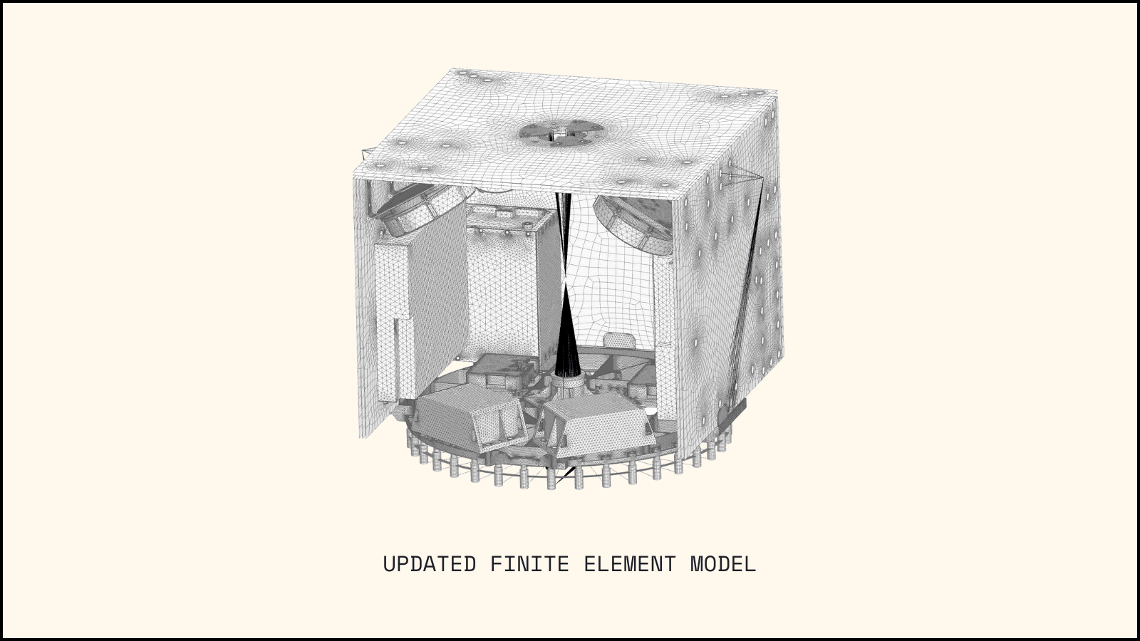
So that was a look at the solar array wings as a break out model. We also need to look at it from the DeepSpace-2 spacecraft side as well. So here on the right you can see a 1D element that represents the wings into their bolt holes with a concentrated mass at the vertex. This is the simplified model that allows for the investigation of the panel behavior for both mode and stress. Higher fidelity versions of this interaction with panel geometry are slated for additional exploration but this allows the team to start seeing the effect of the panels on DeepSpace-2 itself.
Thermal Bounds and Considerations
While the thermal considerations for the bus and solar arrays share similar concepts, solar arrays have specific differences. The fundamental distinction is that solar arrays convert a portion of solar flux from heat to electrical energy, which powers the spacecraft. The efficiency of this conversion depends on several factors, including the temperature of the arrays.
To recap the modes of heat transfer from the previous thermal discussion:
Conduction: Heat transfer through solid bodies making direct contact
Convection: Heat transfer with fluid motion (i.e. gasses and liquids)
Radiation: Heat transfer through electromagnetic waves (Space is a vacuum leaving radiation as the only mode for heat to enter or leave the spacecraft because it is the only mode that does not require a medium.)
The energy balance on the solar arrays can be simplified to the following assuming steady conditions.

Solar arrays are generally fairly isolated from the bus so that conduction does not need to be considered. Depending on the view factor between the bus and the solar arrays, the radiation exchange may need to be considered both for the solar array temperature and for the impacts on nearby components.
Summary
Designing a solar array for space applications demands a careful balance of competing constraints. Engineers must develop a structure robust enough to endure the intense vibrations of launch, yet lightweight enough to comply with strict mass limitations. At the same time, the array must generate sufficient power to operate onboard thrusters and electronics. Material selection plays a pivotal role, requiring careful consideration of electrical and thermal properties, structural strength, and actuation performance. All these design challenges must be met within the bounds of the mission’s specific requirements, budgetary constraints, and rigorous qualification testing standards.