Spacecraft Power 101
Matt Gialich
Introduction
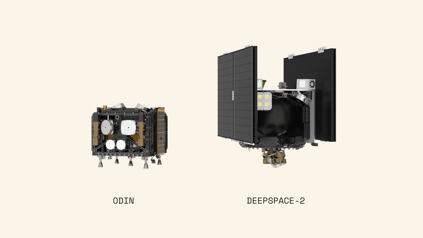
All spacecraft share the same basic power elements: generation, distribution, and energy storage. While these systems can be designed in various ways, most spacecraft employ solar arrays, batteries, and power conditioning and distribution circuits to fulfill these functions. Both of our deep space craft, Odin and DeepSpace-2, have these core components.
Despite these similarities, DeepSpace-2 and Odin feature substantially different power system designs. These differences stem from three key factors: power requirements, build experience, and build schedule.
Odin's tight build schedule forced us to select components based on immediate availability. This narrowed our power system design to focus on one essential goal: integrating available parts while meeting the launch deadline. We succeeded in this. Odin powered up and operated normally for several hours. However, as detailed here, Odin ultimately failed to complete its mission. With DeepSpace-2, we conducted a thorough analysis of Odin's shortcomings and identified opportunities for improvement.
The power requirements differ significantly because not only is DeepSpace-2 a larger spacecraft requiring more power, but it also demands greater reliability. Odin was designed for an asteroid fly-by, which allowed us to use a relatively low-power chemical propulsion system. DeepSpace-2, however, will land on the asteroid, necessitating an electric propulsion system. Therefore, DeepSpace-2 requires significantly higher power generation, lower minimum power consumption, increased energy storage capacity, and more efficient power distribution.
Odin was not only AstroForge’s first deep space craft, but also the first commercial deep space craft ever built. Through its development and launch, we gained significant knowledge and recognized several suboptimal decisions in our core power system design. Now, we’re applying those lessons to enhance every aspect of the DeepSpace-2 power system by using additional development time and incorporate expertise from new team members with even more deep space craft experience.
This is a detailed summary of how those learnings are being applied to DeepSpace-2.
The Power System
The power system is the heart of any spacecraft. It's the most critical system onboard; without power, the spacecraft cannot function at all. For the purpose of this class, let’s break down the power system into three major components: generation (solar panels), distribution (the routing), and energy storage (batteries).
Before diving into the power system details, it's important to understand a key differentiator with AstroForge missions: we operate in deep space. When most people hear the word “spacecraft,” they think of satellites orbiting Earth; however, deep space vehicles face fundamentally different power challenges. Unlike spacecraft in Low Earth Orbit (LEO), we don't experience sun shading from moving behind the planet. This creates extreme temperature variations—one side of our spacecraft becomes intensely hot while the opposite side remains extremely cold. Unlike spacecraft in Geosynchronous Orbit (GEO), we don’t maintain a fixed pointing attitude, or have a dedicated "sun-facing side." We’ll explore this further when discussing thermal considerations, but these factors play a major role in our solar array system design.
Block Diagrams
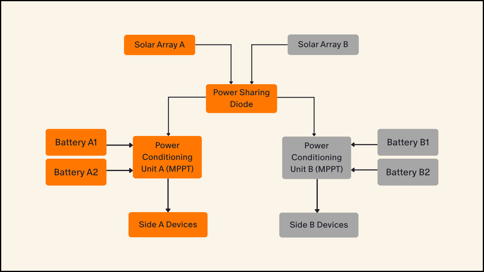
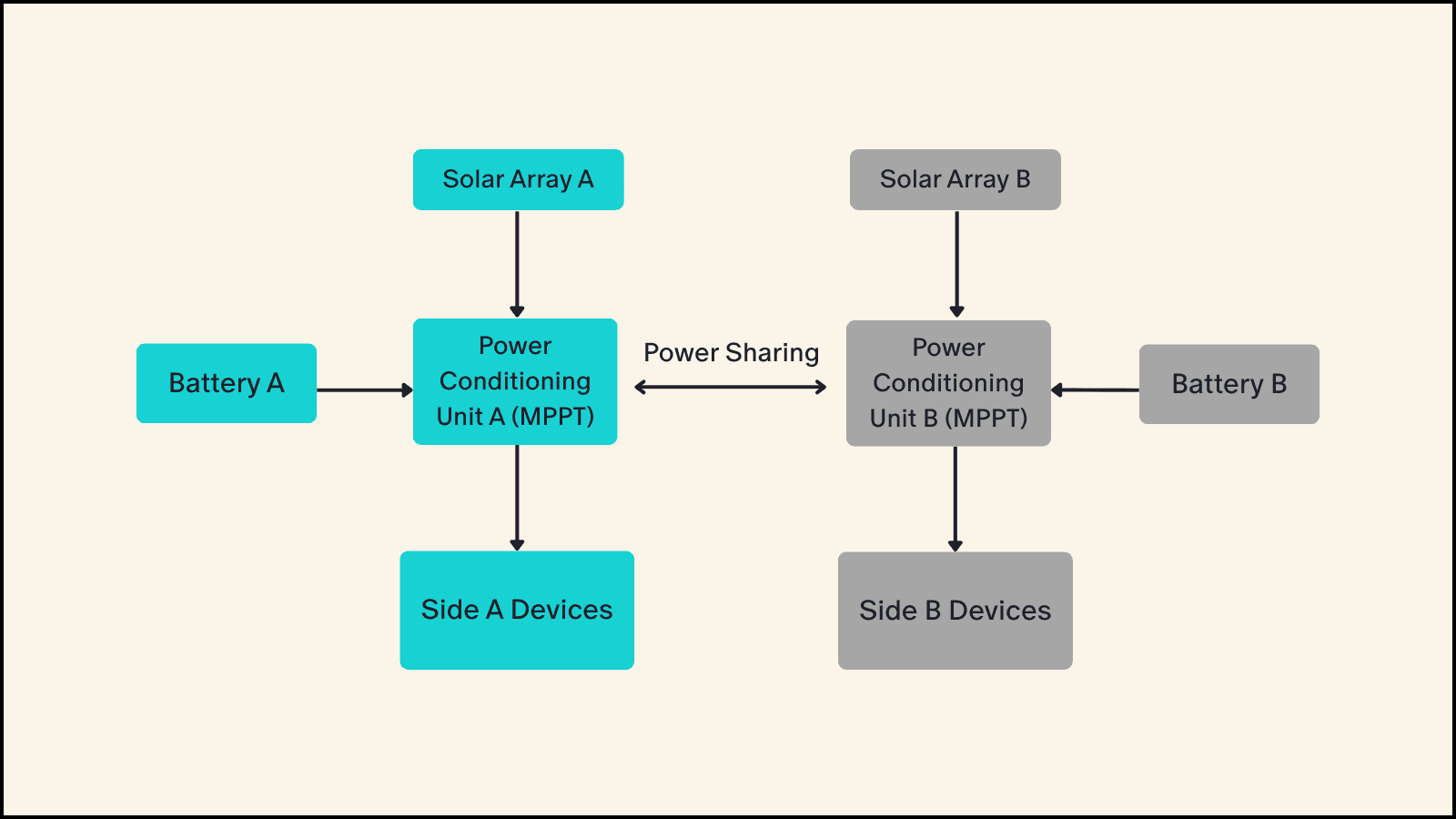
Below you’ll find high-level block diagrams showing the components of both spacecraft power systems. These architectural diagrams for Odin and DeepSpace-2 provide a useful reference point for understanding the critical processes we’ll discuss in detail.
Odin Power Design
DeepSpace-2 Power Design
Power Budgets
The first step in designing a power system for any spacecraft is creating a power budget. This budget determines how large the solar arrays and batteries need to be. Power budgets rank among the most detailed and technical documents in spacecraft design. Variables such as temperature, distance from the sun, and lifetime performance significantly impact these calculations.
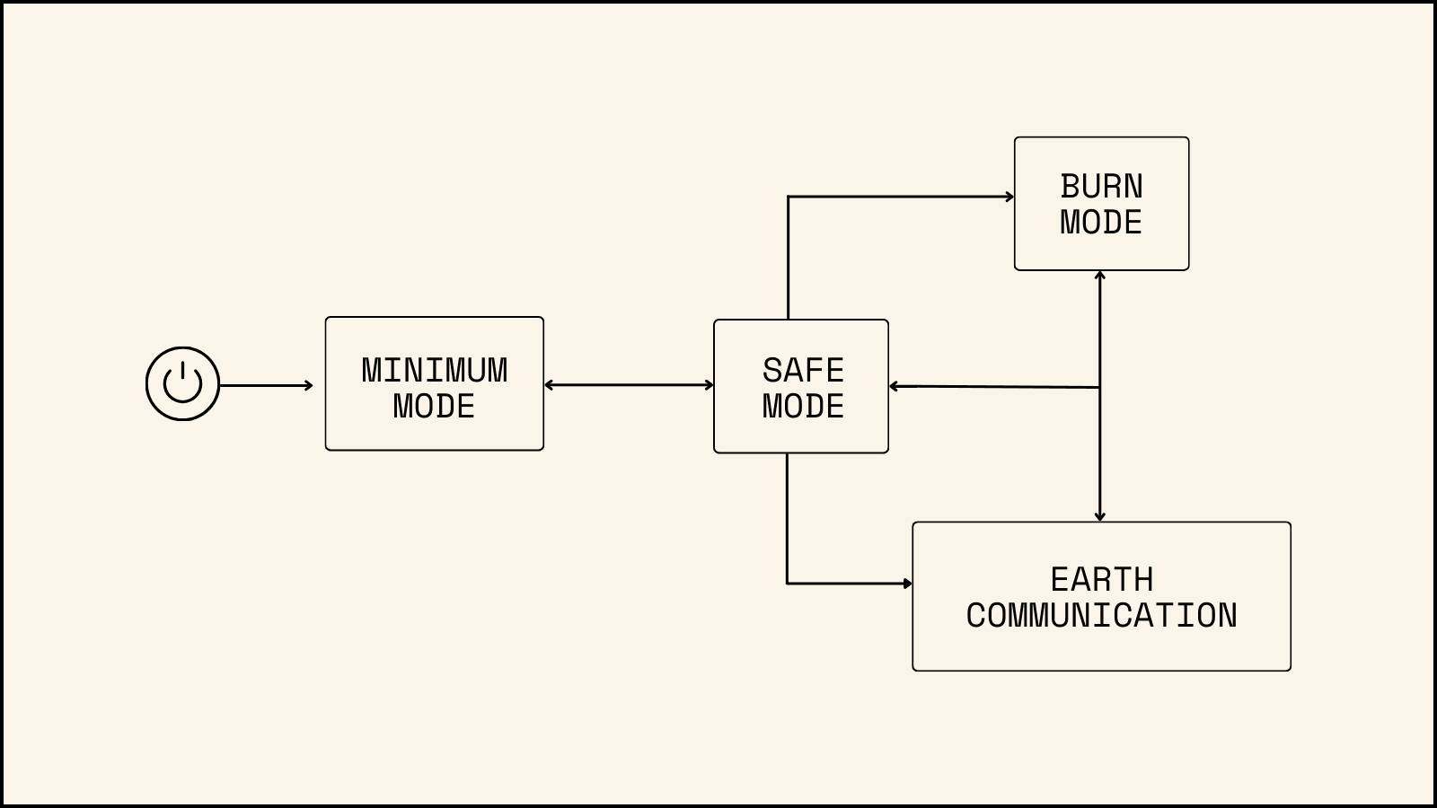
We organize the power budget into what we call Modes. These modes represent operational states that the spacecraft enters during different mission phases. For example, when the thrusters are firing, we call this "burn mode," and all calculations are based on the power requirements of the thrusters. The overall mode structure remained consistent between Odin and DeepSpace-2.
The spacecraft operates in 4 primary modes:
Minimum Power - Worst case scenario where we minimize power draw to preserve/charge batteries and wait for commands from Earth, using only a low duty-cycle communication beacon
Safe - Stabilize the spacecraft and communicate with Earth in a predictable pattern
Burn - When the propulsion system is actively operating
Earth Communication - High data rate communication with Earth for mission data downlink
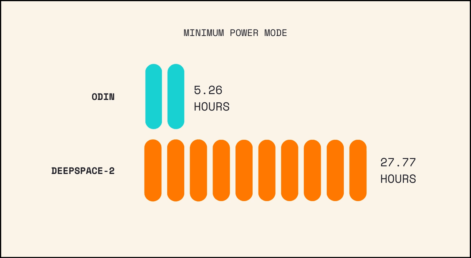
Minimum Power Mode
Let’s start with the worst-case scenario. If things are going very wrong and the battery state of charge continues to drop, even after reverting to Safe Mode, the spacecraft's last line of defense is Minimum Power Mode. In this mode, the spacecraft drops to a minimum power state to extend the remaining battery charge as long as possible. Attitude control ceases, radio transmissions drop to a very low duty cycle, and most avionics systems shut down except for the bare essential systems keeping the satellite alive.
Power Generation (watts) | Used Power (watts) | Relative % of Power Generation | Battery Energy Storage (Wh) | Time Alive on Only Batteries (hours) | |
|---|---|---|---|---|---|
Odin | 160 | 76 | 48% | 400 | 5.26 |
DeepSpace-2 | 2047 | 36 | 2% | 1000 | 27.77 |
The contrast between Odin and DeepSpace-2's power systems is evident here. Odin had a significantly higher minimum power requirement than DeepSpace-2 due to its avionics design. Odin featured two power-hungry flight computers that couldn't be turned off, each consuming 35W of power. With these computers and the two receivers running, Odin's lowest possible power draw was nearly half the capacity of its solar arrays.
For DeepSpace-2, we redesigned the architecture to allow the flight computers to shut down and switch to a low-power microcontroller that handles only essential spacecraft maintenance. This design enables us to consume just a fraction of the power described above, despite having a larger spacecraft.
Safe Mode
Now, let's look at Safe Mode. This is the mode that activates when something goes wrong - every spacecraft has one.
The behavior of the spacecraft in Safe Mode is simple: it point its arrays toward the sun, spins about the sun vector while periodically broadcasting telemetry on the transmitters, and awaits further instructions. The receivers remain active throughout, allowing the spacecraft to receive commands at any time. If the spacecraft successfully orients itself towards the sun, it can maintain this mode indefinitely. However, if it fails to align its arrays with the sun and battery charge continues to drop, the system will revert to Minimum Power mode.
Power Generation (watts) | Used Power (watts) | Relative % of Power Generation | Battery Energy Storage (Wh) | Time Alive on Only Batteries (hours) | |
|---|---|---|---|---|---|
Odin | 160 | 101 | 63% | 400 | 3.96 |
DeepSpace-2 | 2047 | 258* | 13% | 1000 | 3.87 |
* Increased radio power for additional distance and duty cycle for downlink opportunities compared to Odin
Earth Communication Mode
I’ll explain this further in the communication section, but it’s important to understand that spacecraft data rates aren’t fixed. Both Odin and DeepSpace-2 operate at very low data rates by default, increasing only when commanded to do so. Earth Communication Mode is simply when we transmit data at these higher rates.
Power Generation (Watts) | Power Usage (Watts) | Relative % of Power Generation | Battery Energy Storage (Wh) | Time Alive on Only Batteries (hours) | |
|---|---|---|---|---|---|
Odin | 160 | 110 | 69% | 400 | 3.6 |
DeepSpace-2 | 2047 | 345 | 17% | 1000 | 4.8 |
As you can see, DeepSpace-2 shows a significant power increase in Earth Communication mode compared to Odin. This improvement primarily comes from implementing a more powerful solid state amplifier for the radio.
Burn Mode
In Burn Mode, the spacecraft activates its propulsion system and fires the thrusters. This critical mode propels us out of Earth’s system and into deep space. There are significant differences between how Odin and DeepSpace-2 utilize this mode.
Total Power (watts) | Used Power (watts) | Relative % of Power Generation | Battery Energy Storage (Wh) | Time Alive on Only Batteries (hours) | |
|---|---|---|---|---|---|
Odin | 160 | 260 | 163% | 400 | 1.54 |
DeepSpace-2 | 2047 | 1432 | 70% | 1000 | 0.7 |
Notice there are several key differences between the spacecraft. First, Odin’s power consumption while firing the thrusters exceeded its solar array generation by 63%. This meant we had to draw from batteries whenever thrusting, limiting burns to approximately one hour before needing to stop and recharge. This constraint severely restricted our burn sequence design options.
This was not an oversight. With a chemical propulsion system, burns are naturally short, so operating power-negative during these bursts was fine. We implemented safeguards to ensure that Odin would exit Burn Mode and enter Safe Mode if battery charge dropped below a certain threshold.
Second, DeepSpace-2's power requirement is dramatically higher than Odin’s because it uses a Hall Effect Thruster, which consumes 1240W of power in max thrust configuration. However, DeepSpace-2's solar arrays are deliberately oversized to provide sufficient margin for this case, enabling the thousands of hours of continuous thrust required to rendezvous with the asteroid.
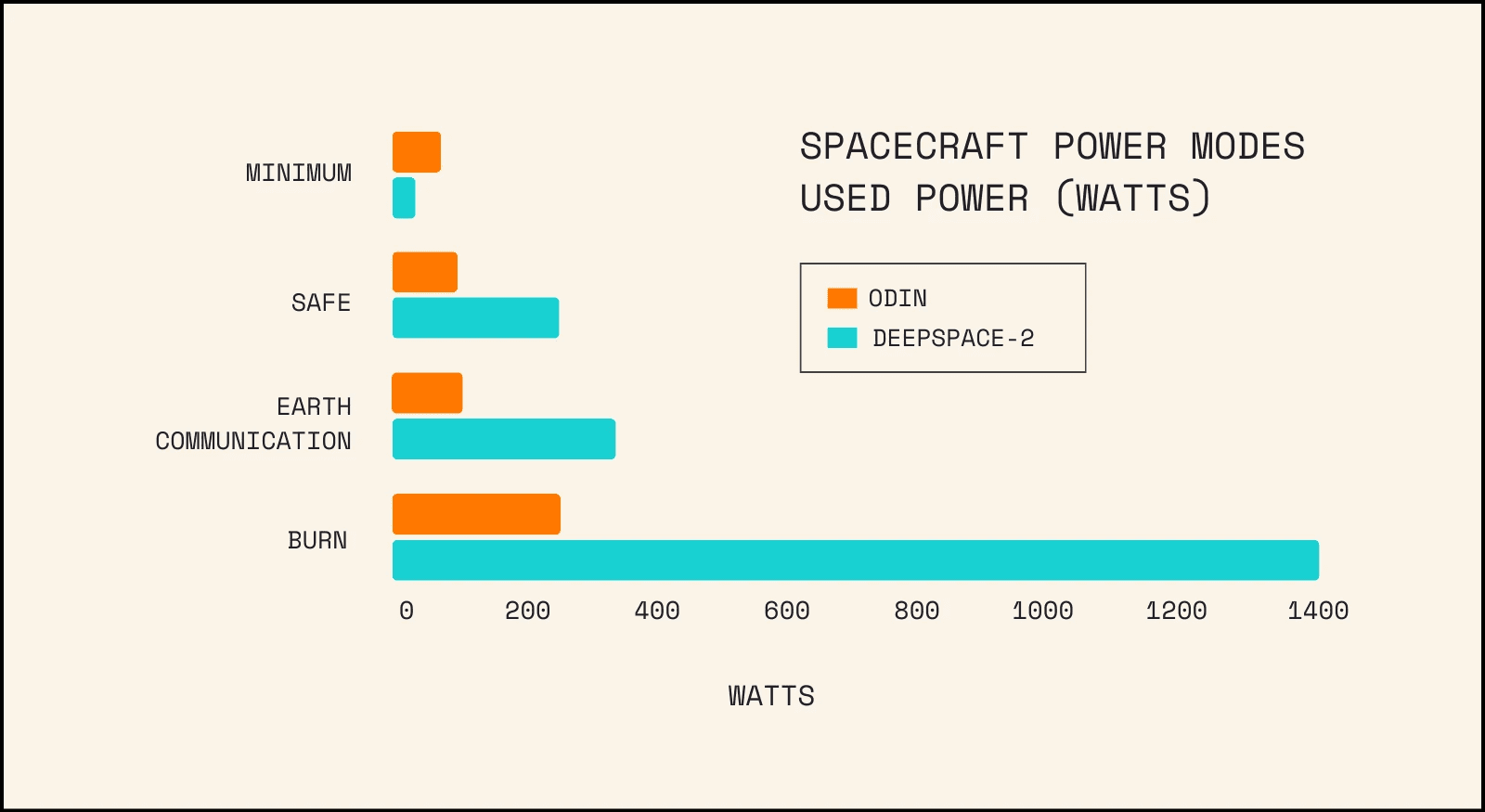
Summarizing and comparing power generation and consumption:
Solar Arrays - How We Generate Power
Like all commercial spacecraft, both Odin and DeepSpace-2 use solar panels for power generation. Alternative methods, such as Radioisotope Thermoelectric Generators (RTGs), are impractical due to their prohibitive costs and strict regulatory requirements.
Before examining the differences between our two spacecraft’s solar arrays, let's explore the key factors affecting solar panel power generation. The three main variables are the offset angle, distance from the sun, and cell temperature.
Solar Offset Angle: All power generation figures mentioned so far, and discussed below, assume solar panels directly facing the sun (i.e. 0° offset). As the panels tilt away from the sun, power generation decreases according to a cosine law. The table below illustrates how offset angles affect power generation.
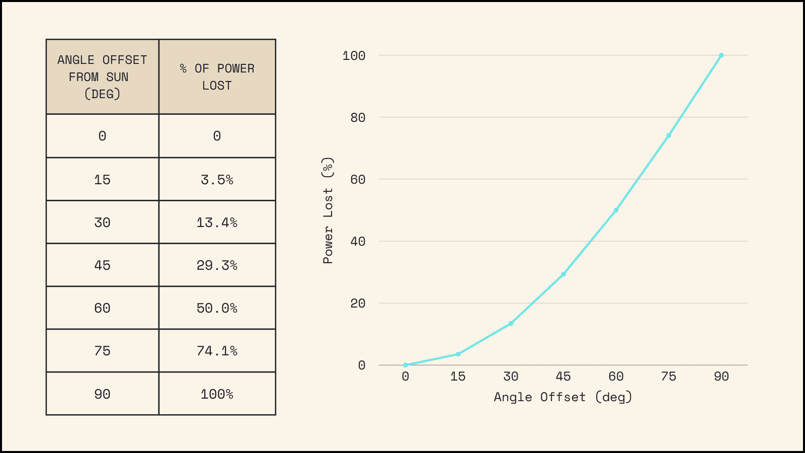
This simple chart illustrates an important concept: our solar pointing accuracy doesn’t need to be perfect. The relationship between angle and power generation is non-linear, allowing us to capture most of the solar flux even with slight pointing errors.
Distance from the Sun: For satellites in Earth’s orbit, the distance to the sun remains relatively constant at 1AU (astronomical unit—the average Earth-Sun distance of approximately 93 million miles or 150 million km). However, we cannot make this static assumption for our mission. As we travel to the asteroid, our distance from the sun will vary significantly. This is why our spacecraft is designed to operate in a range of 0.9AU to 1.1AU from the sun.
At 1AU, the average solar power density is 1367W/m². This power density follows an inverse square law as distance from the sun changes. For example, if you double your distance from the sun, the power density drops by a factor of 4. For our mission, which operates between 0.9AU and 1.1AU, we will experience power densities ranging from 1725W/m² (at 0.9AU) to 1155W/m² (at 1.1AU). This is a massive variation for a relatively small change in distance.
Cell Temperature: The other major factor in solar power generation is the effect temperature has on solar arrays. At higher temperatures, solar panels operate less efficiently. The plot below shows the power generation of the DeepSpace-2 solar cells at 1AU.
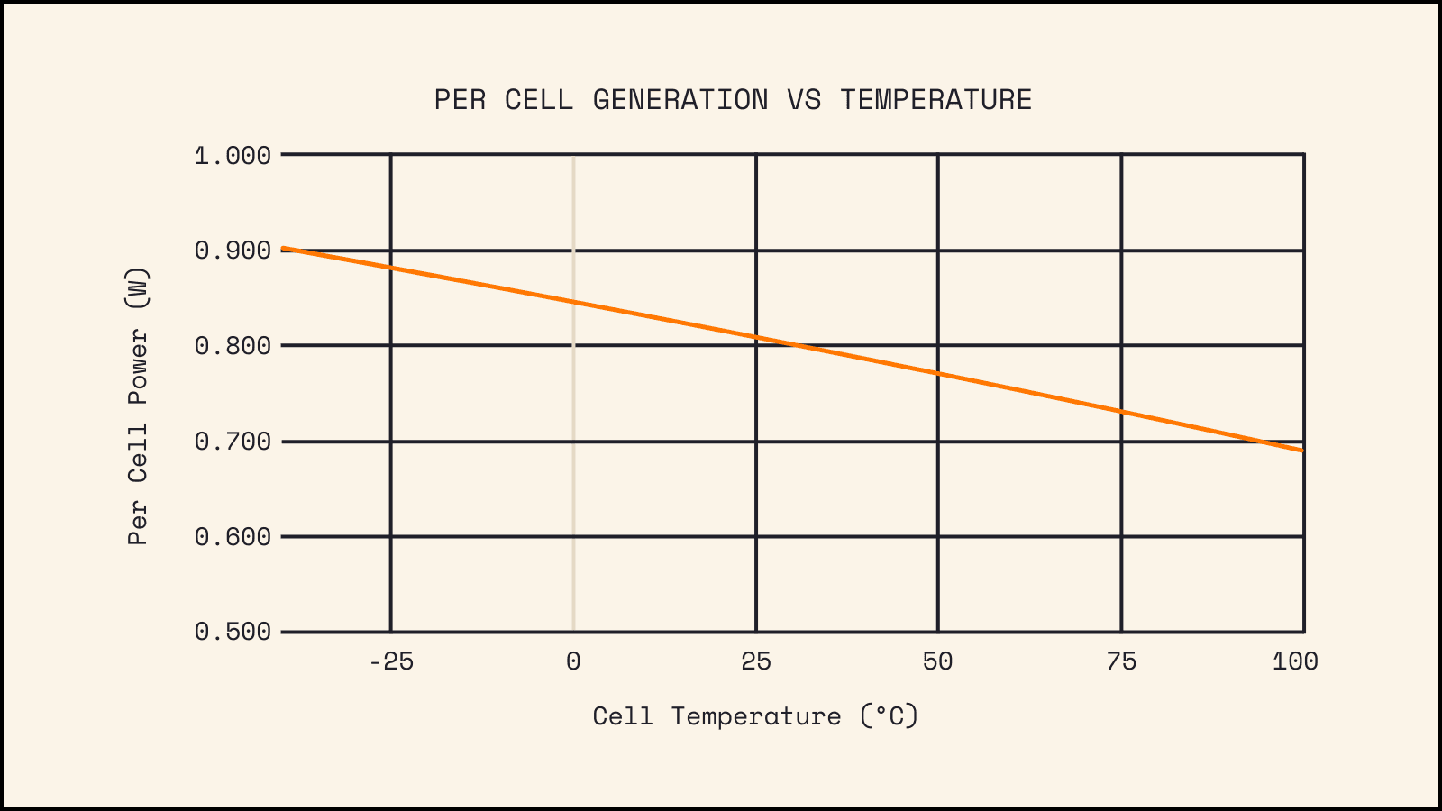
Unlike Earth-orbiting satellites, our spacecraft’s solar arrays receive constant illumination from the full power of the sun (except when we deliberately point them away). This constant exposure means our arrays operate at the hotter end of the temperature curve shown above. Notice how the power generation drops from approximately 0.9W/cell at -40°C to less than 0.7W/cell at 100°C—a roughly 20% decrease in power generation due to higher temperatures.
These three factors (offset angle, distance from sun, and temperature) are interrelated, creating complexity in power budget calculations. At 0.9AU, for example, our solar cells become hotter and less efficient, yet they benefit from higher solar power density, ultimately generating more overall power. Similarly, when we angle the solar arrays away from the sun, they become cooler but generate less power due to the reduced solar exposure.
Additional factors affect solar power generation, including radiation effects such as coverglass darkening and atomic displacement. We account for these at the mission level rather than the spacecraft level. These factors lead us to budget for the cell degradation of 10% per year-long mission. Real-world data suggests this figure is actually closer to 2% per year, or 4% over the entire mission. However, with such a critical system, we prefer to err on the side of caution, so we design our missions to last for two years to compensate for the inevitable loss of solar cell efficiency.
For the sake of simplicity in the comparisons below, we will assume arrays pointing directly at the sun (0° offset) at 1AU. We will not ignore temperature effects on power generation.
Odin: The panels for Odin were made by Pumpkin Space Systems and featured standard triple-junction cells on a fiberglass (printed circuit board) substrate. The cells were then covered with glass for radiation protection. We anticipated a degradation rate of about 10% per year due to radiation effects, meaning our two-year mission would lose 20% of total power generation.
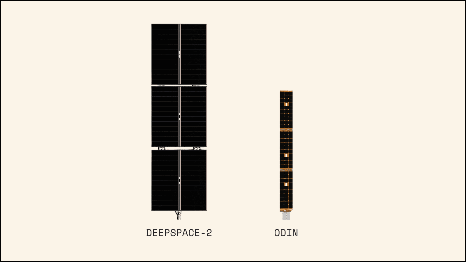
The solar system consisted of two wings, each with three panels. Each panel can generate 30 watts of power when facing the sun, giving us 90 watts per side and 180 watts for the entire spacecraft in an ideal configuration at 1AU.
The panels were built as six independent strings, so if any one string failed, we would lose only 1/6th of the total power generation.
DeepSpace-2: The solar panels on DeepSpace-2 maintain a similar configuration but are significantly larger. DeepSpace-2 has two wings with three panels each. This time, however, the design was determined by the need to fit inside the Falcon 9 fairing rather than by available construction techniques.
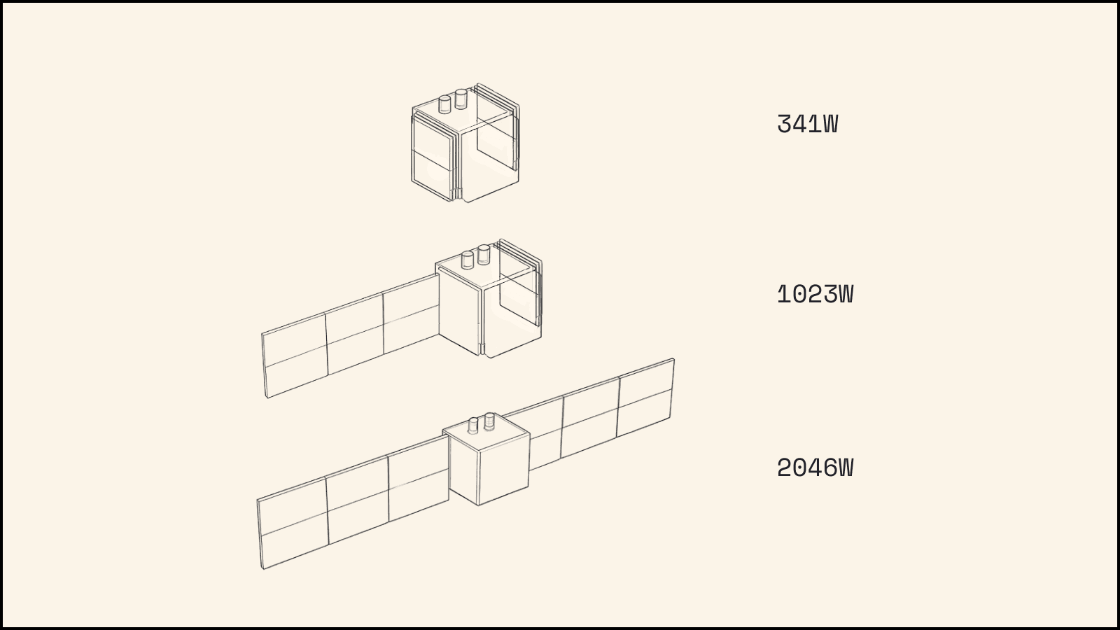
Each panel generates 341 watts of power at 1 AU using a semi-rigid cell structure that’s approximately 25% efficient, which means that DeepSpace-2's panels can convert approximately 25% of the solar energy that hits them into usable electrical power. For radiation protection, we’ve replaced the glass with a polymer spray that provides equivalent protection. We expect these panels to degrade at only 4% per year, resulting in a 8% power loss over the mission lifespan.
We attach the semi-rigid cells to a honeycomb sandwich panel substrate, resulting in an incredibly lightweight design of ~120W/kg including panels, hinges, wiring, and hold down mechanisms. The panels feature two rows of modules each, with 12 independent strings across both wings. If any panel or string fails, the mission can continue with reduced power generation capacity.
When designing the solar array system, we prioritized the spacecraft’s ability to stabilize and communicate with Earth even if the deployment mechanism failed. If no arrays deploy, we still have 341W from a single panel - enough to operate in Safe Mode and maintain communications with Earth.
Further, if only one wing deploys, DeepSpace-2 can still generate up to 1023W, allowing for a lower-power Thrust Mode of 450W compared to the 1250W needed for peak thrust.
This is the single largest lesson from Odin. While the panels themselves were single, or in some cases multi-fault tolerant, the release mechanism was not. For DeepSpace-2, it was a requirement from the start that we would not lose the mission if the panels did not deploy. While we will be in a severely degraded state — having these large panels will give us months, if not years, to attempt to fix the issue.
Batteries - How We Store Energy
Batteries are a crucial component of any spacecraft. They store surplus energy for later use whenever the spacecraft’s power needs exceed what the solar arrays are generating at that moment. For Earth-orbiting satellites, batteries play a vital role during eclipse periods—when the satellite passes through Earth’s shadow (nighttime). During these periods, batteries keep all systems running when solar arrays receive no sunlight.
Our mission is a bit different. In most launch scenarios, we experience no eclipse at all, so we don’t need to worry about passing through Earth’s shadow. Instead, our batteries serve three key functions: helping the system start up, keeping us operational if we lose solar pointing, and handling transient power surges when the propulsion system activates.
Batteries are rated by their energy storage capacity, typically in units of watt-hours (Wh). For example, a 100 Wh battery can power a 100W load for 1 hour or a 1W load for 100 hours. This metric helps us understand how long our system can operate on battery power alone.
Odin:
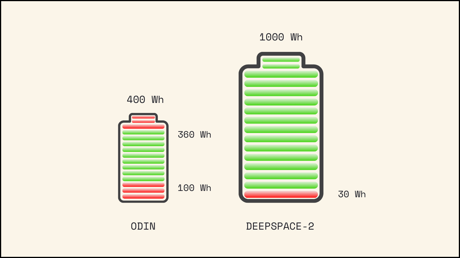
Odin utilized four 100Wh batteries, two per power string, meaning each string had access to 200Wh of energy. Odin could not share battery energy between Side A and Side B. An additional drawback of the off-the-shelf power system was a fixed maximum charge of 90% of full capacity. In reality, each battery had only 90Wh of usable energy storage. Under high loads, the battery would “brown out” at a state of charge less than 25%, further limiting our usable energy to 65Wh per battery—a significant limitation. With all four batteries fully charged, Odin had 260Wh available to use.
For a spacecraft with a minimum power mode of ~75W, this amount of energy provided little troubleshooting time when running on batteries alone. If the spacecraft was running in Minimum Power mode using only battery power, we had approximately 3.5 hours before depleting the batteries.
DeepSpace-2:
On DeepSpace-2, we’ve significantly increasing battery capacity relative to the spacecraft’s minimum power draw. We now have two 500Wh batteries, providing over 1000Wh for the entire system. By designing the power management system in-house rather than using off-the-shelf systems, we’re no longer limited by pre-made design choices. This allows us to share battery energy between Side A and Side B, giving each side full access to the entire 1000Wh capacity. Our battery charge circuit can also charge the batteries to their full 100% state, maximizing our available energy storage.
We’ve further enhanced DeepSpace-2's resilience by reducing the spacecraft’s Minimum Power mode to just 36W (approximately the same amount of power required to operate a mini desktop fan). Operating off batteries alone in this mode, we can function for over 27 hours on a single charge. This provides us a full day to diagnose any issues and implement fixes if we ever need to operate solely on battery power—though this remains an unlikely scenario.
Power Board - How We Distribute the Power
Generating power with solar arrays and storing it in batteries doesn't do you any good if you can't distribute the power out to the systems that need it, like your computers, sensors, radios, and actuators. That is where the power distribution comes into play.
A regulated power system will keep the bus voltage constant, in most cases 28V. It gives you the advantage of having a constant voltage for all downstream loads, and not having to protect every component for overvoltage damage. But it does lower the overall efficiency, and adds some mass to the system as the power regulators need to be larger.
An unregulated system is where the bus is not held at any special voltage and is instead dictated on the high end by the solar input, and on the low end by the battery. These systems are higher efficiency and simpler, but require that all your components can tolerate variable loads and have built-in overvoltage protection. An unregulated system also does not operate the solar panels at their peak efficiency.
Both Odin and DeepSpace-2 used a regulated power system. We purchase components from other vendors, such as our reaction wheels, star trackers, and radios. Making sure the supplier was compliant with an unregulated system would require a deep dive into their systems, and getting it wrong could mean a simple loss of a mission-critical system. For the sake of reliability, regulating the power was the safest choice.
Distribution
Generating power with solar arrays and storing it in batteries serves no purpose if you can't distribute that power out to systems that need it—your computers, sensors, radios, and actuators. This is where power distribution becomes essential.
A regulated power system maintains a constant bus voltage, typically 28V. This provides the advantage of consistent voltage for all downstream loads, eliminating the need to protect each component from overvoltage damage. However, it does reduce overall efficiency and adds weight to the system due to larger power regulators.
In contrast, an unregulated system allows the bus voltage to vary—determined by solar input at the high end and battery voltage at the low end. These systems offer higher efficiency and simpler design, but require all components to tolerate variable voltages and include built-in overvoltage protection. Additionally, unregulated systems don’t operate solar panels at their peak efficiency.
Both Odin and DeepSpace-2 use regulated power systems. Since we purchase some components from external vendors (reaction wheels, star trackers, and radios), ensuring these products can handle an unregulated system would require more extensive system analysis and testing. Getting it wrong could result in losing mission-critical systems. For reliability’s sake, regulating the entire power bus was our safest choice.
Distribution
The power distribution system also conditions power from solar arrays into a usable format for the vehicle. While there are several ways to do this, all AstroForge spacecraft have used an algorithm called Maximum Power Point Tracking (MPPT). In MPPT-based systems, the power conditioning circuit identifies the optimal operating point of solar cells to extract maximum power. This allows us to precisely control the power drawn from the solar arrays to match our exact needs.
Another key function of the power distribution system answers the question: what do we do with excess power? When solar arrays generate more power than needed—for example, 200W when only 100W is being used—the surplus 100W must go somewhere, typically converting to heat. Different spacecraft handle this scenario in various ways. One advantage of MPPT systems is their ability to control power extraction from the solar arrays so that excess energy (heat) remains on the arrays themselves. This is accomplished by deliberately operating away from the maximum power point.
Odin:
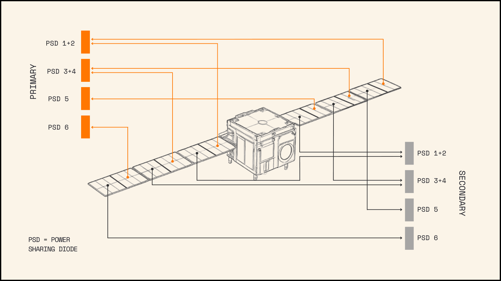
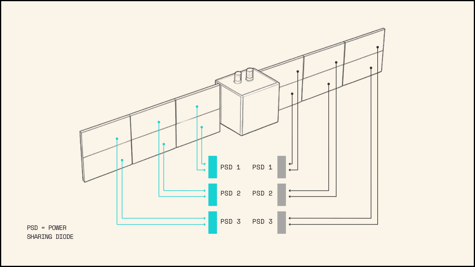
For Odin, we used commercial-off-the-shelf power conditioning systems and built our own power distribution circuit. We installed two Power Conditioning Units with independent MPPT algorithms to distribute power to both A and B Sides. We wanted each side to have access to 100% of the solar power, so we placed a power sharing diode between the solar arrays and MPPT circuits. In hindsight, this proved to be problematic. The MPPT circuits weren’t designed to operate in parallel and had no awareness of each other. As a result, both sides attempted to extract maximum power from the same solar array simultaneously, causing the solar array voltage to collapse.
We identified this issue during testing and implemented a workaround by artificially limiting the power to one side for each solar string. For instance, we restricted MPPT B Solar Input #1 to a minimal power level (100mW) while allowing MPPT A Solar Input #1 (connected to the same solar string) to operate without limitations. This solution enabled the two MPPT circuits to function together properly, but resulted in approximately 5% less total power available to the system. Additionally, the power sharing diode created further power losses, which reduced the peak power generation capability.
Another issue with the off-the-shelf MPPT was its longer switching timing. When the propulsion system shut down suddenly, a surge of energy would flow through the system and need somewhere to go. In our design, this “somewhere” was a shunt—which we called the “overvoltage” shunt. This was essentially a large piece of metal bolted to the spacecraft to convert the excess energy to heat. While this wasn’t a design flaw, it did cause some issues during subsequent testing and integration.
During one assembly of the vehicle, the shunt circuit was damaged during handling, and we didn’t notice until powering up the system. We regularly subject the power system to large transients that require energy to flow into into the shunt during testing. However, this time, the shunt circuit was open (meaning power couldn’t flow into it). With nowhere to go, the power surged back and blew up the MPPT circuit. Smoke billowed out of the vehicle and we were forced to do an emergency replacement just two weeks before shipping to the launch site. On DeepSpace-2, we’ve eliminated the need for this shunt altogether.
DeepSpace-2:
The biggest advantage we have going from Odin to DeepSpace-2 is that we now control 100% of the power conditioning and distribution system design, as we’re building it in-house. While we’re still using MPPT technology, we now control the entire design process. This allows us to make critical decisions that significantly improve our system’s robustness.
First, we’ve eliminated shared solar arrays between the two sides of the power system. DeepSpace-2 features dedicated strings for MPPT Circuits A and B. This immediately eliminates the diode losses and efficiency issues that occur when two independent MPPT circuits operate in parallel. To maintain full power accessibility between sides, we’ve added a power sharing circuit that connects both power buses, creating a common power pool. This gives both sides access to 100% of the spacecraft’s available power and energy.
With full design control, we’ve also eliminated the need for an overvoltage shunt. Though DeepSpace-2 will still experience the large power transients that typically require a shunt, we’ve developed a smarter solution. Since these power surges are quite short (less than 50ms), we’ll redirect excess power back to the battery until the MPPT circuit can reduce power from the solar arrays. Effectively, the battery serves as our overvoltage shunt, eliminating the need for additional circuits or external devices.
We continue to push the boundaries of speed in deep space exploration, with less than 12 months scheduled between the Odin and DeepSpace-2 launches. Through DeepSpace-2's design, build, launch, and operations, we will inevitably learn more lessons and continue to improve our power systems for future mining vehicles. DeepSpace-2 already represents a significant leap in capability compared to Odin. With our entire team focused on perfecting every detail of DeepSpace-2, we’re confident in our next mission’s success.