Spacecraft Structures
Matt Gialich

Spacecraft Structures
All space missions share one fundamental requirement: their hardware must survive the violent environment of launch and then be properly positioned in space to fulfill their purpose. Whether it’s a telescope expanding our understanding of the universe, telecommunications equipment improving Earth's communication networks, or ambitious projects like asteroid mining, all equipment must be transported to its intended location. The James Webb Telescope, for example, didn’t simply materialize in its orbit.
Spacecraft structures serve this essential purpose. They function as vehicles that support, deploy, protect, and correctly orient various equipment and instrumentation. These structures provide secure attachment points for major components like the spacecraft separation system, propulsion system (propellant tank, thrusters, etc.), navigation components (reaction wheels, star tracking equipment, etc.), and solar arrays. A well-designed structure must withstand all loads and forces the spacecraft will encounter while preventing these forces from affecting sensitive attached equipment. This highlights a crucial distinction between strength and stiffness, which we will explore further later.
Solar arrays also have a variety of unique structural requirements and load cases. They are generally large (relative to the size of the rest of the spacecraft bus) and thin; this allows maximization of available surface area to mount cells for generating power while also minimizing their overall mass. These somewhat competing requirements make array design a unique and complex challenge from both a configuration, strength, and stiffness perspective, and as such we will be devoting a separate blog post exploring array design that will be available in two weeks.
Now that we’ve introduced the concept of spacecraft structures, let’s examine the key aspects that must be considered when defining a spacecraft mission and the corresponding structural requirements.
Requirements
What are the requirements of a mission? While the following list is not exhaustive, it includes some key questions that should be documented to ensure the engineering team understands the design requirements:
What is the maximum allowable mass for the entire spacecraft?
What are the maximum expected loads/forces that the vehicle will experience?
Does the vehicle need to reenter Earth’s atmosphere?
Is the spacecraft expected to land on any celestial body?
What temperature extremes will the vehicle be subjected to (coldest and hottest cases)?
What size limitations exist for the spacecraft? I.e., is there a defined volume that the spacecraft must stay within during launch to avoid intruding on other payloads?
How will the spacecraft connect to the launch vehicle?
What separation mechanism will be used to detach the spacecraft from the launch vehicle in a controlled manner?
What safety factors should be applied when reporting margins?
What are the hardware-specific requirements for the various equipment components on the spacecraft?
Establishing a detailed, well-documented understanding of mission and vehicle requirements as early as possible helps set a team up for success.
Applying the Above to DeepSpace-2
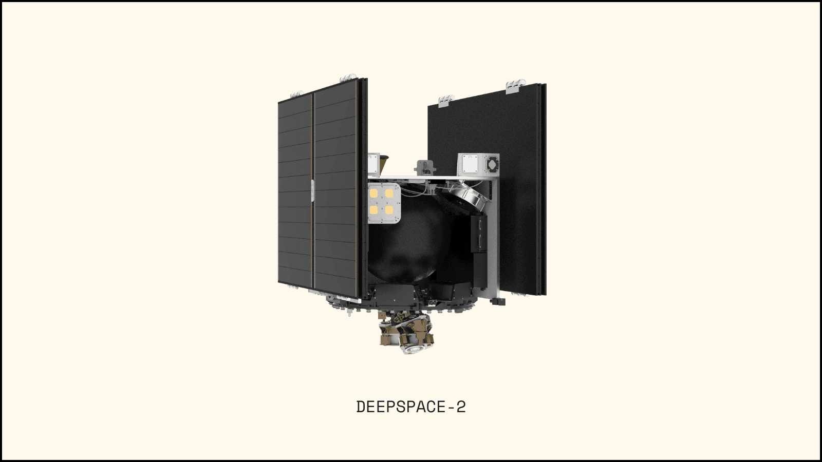
DeepSpace-2 is launching to space in what’s known as a ride share program. This means we aren’t buying a rocket launch dedicated to DeepSpace-2. Instead, Intuitive Machines (IM) has purchased a rocket launch from SpaceX to travel to the moon, and we’re essentially hitching a ride by purchasing a ticket from IM. We have purchased a 200kg mass budget from IM. Though the SpaceX Falcon 9 could potentially carry more, we are contractually limited to 200kg. Exceeding this limit would disqualify us from the mission.
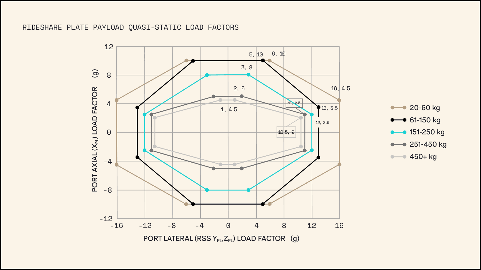
With this information, we can answer many of the questions listed above using SpaceX’s Rideshare Payload User’s Guide (Rpug):
Our vehicle mass is 200kg
Per table 6-4 and the graph below, the Quasi-Static Load Factors for a 200kg payload are 8.0g (where g = Gravity) for axial loads and 12.5g for lateral loads, respectively.
But what does this mean?
If a bracket holds a hardware component and bolts directly to the spacecraft primary baseplate (more detail on the baseplate later), and that hardware has a mass of 5kg, the bracket must be strong enough to support more than just 5kg. It must support:
5kg x 9.81 m/s^2 x 12.5 = 613.125 Newtons of force in the lateral directions, and;
5kg x 9.81 m/s^2 x 8 = 392.4 Newtons of force in the axial direction.
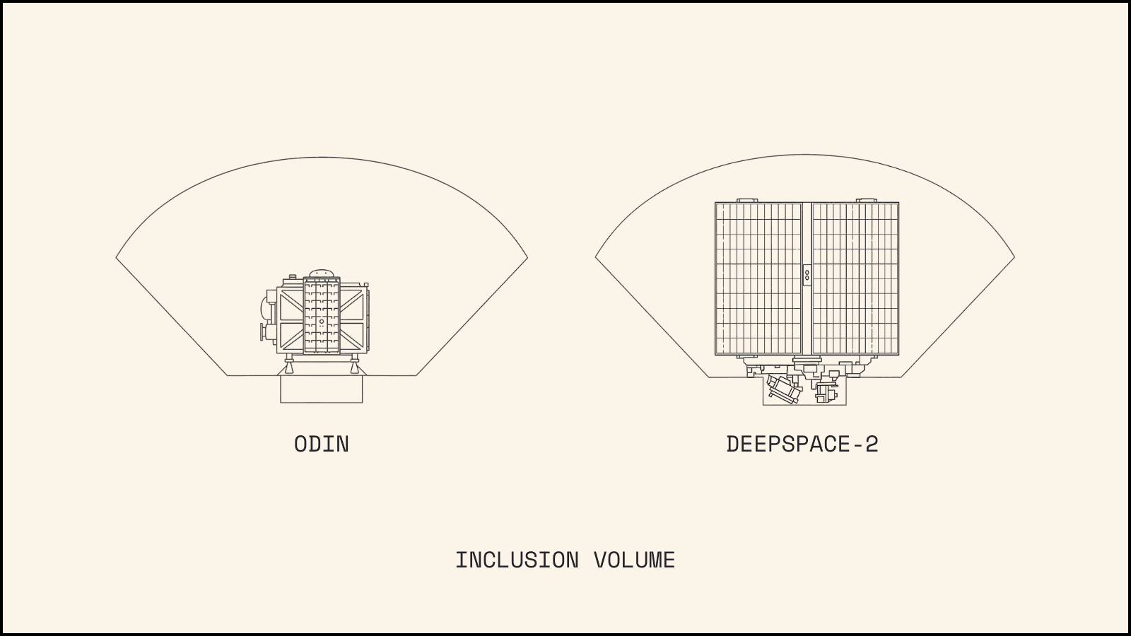
Furthermore, knowing our maximum allowable mass of 200kg and our specific launch vehicle - a SpaceX Falcon 9 rideshare with an XL Plate with Internal Inclusion - provides critical structural parameters. This information defines both the inclusion volume our spacecraft must maintain during launch and the interface geometry between our spacecraft and the launch vehicle. Specifically, we’ll be using a 24 inch bolt circle for mounting. These easily obtained specifications provide valuable guidance for mission design and structural requirements.
Understanding Major Bill of Material Line Items
Before progressing too far with vehicle design, you must identify what the vehicle will transport. While this seems obvious, components are rarely fully defined and selected before significant structural design work must begin.
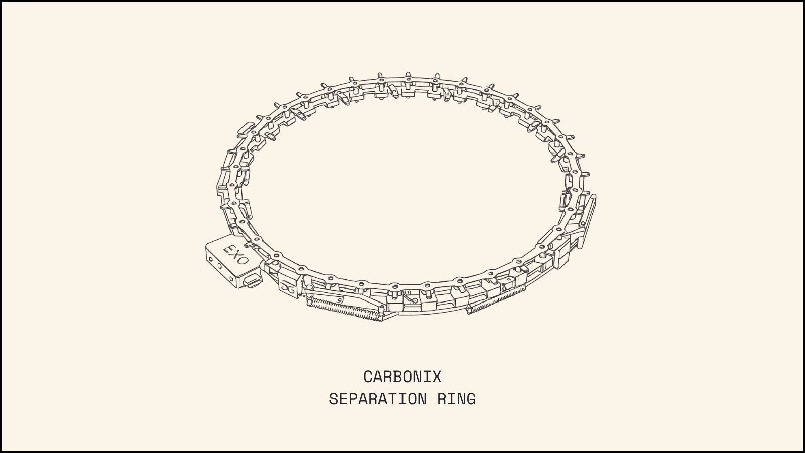
For DeepSpace-2, we’ve established that we’ll use a 24” bolt circle to mount to the launch vehicle. This allows us to select a separation system that: a) accommodates this 24” bolt circle, b) supports our 200kg vehicle mass, and c) meets the Payload Separation requirements specified in Section 3.3 of the SpaceX Rpug document.
We chose Exolaunch’s CarboNIX ST separation ring. Based in Germany, Exolaunch has established flight heritage with reliable separation mechanisms and has completed multiple missions on SpaceX Falcon 9 rockets.
This selection represents perhaps the most important major BOM item, as it enables meaningful progress on the primary structure baseplate design.
Many other important components must be selected to properly define the interfaces between vendor-supplied parts and our AstroForge spacecraft design. These include batteries, propellant tanks, thrusters, PPUs, reaction wheels, and numerous other systems.
The baseplate, however, is the foundation of the spacecraft’s primary structure. It interfaces directly with the separation system (CarboNIX), which then bolts directly to the rocket. The remaining components can be integrated into the design as it progresses.
Quick Note on a Baseplate
I’ve used the term “baseplate” several times in this post. Let’s explore this crucial piece of hardware in more detail.
First, what is a “primary structure”? It refers to the structural elements through which all forces and loads travel. During launch, all forces experienced by the spacecraft must eventually transfer out of the spacecraft and into the rocket. For example, a bracket holding a 5kg component doesn’t experience the forces affecting a neighboring bracket supporting a 3kg component (simplified). However, when both brackets mount to the same panel, that panel bears the combined loads of both brackets.
Consider a two-story house as an analogy. The rafters supports the roof’s weight, the second-story framing supports both the rafters and the roof, while the first-floor supports everything above it. At the bottom, the foundation supports the entire structure and transfers all forces into the ground.
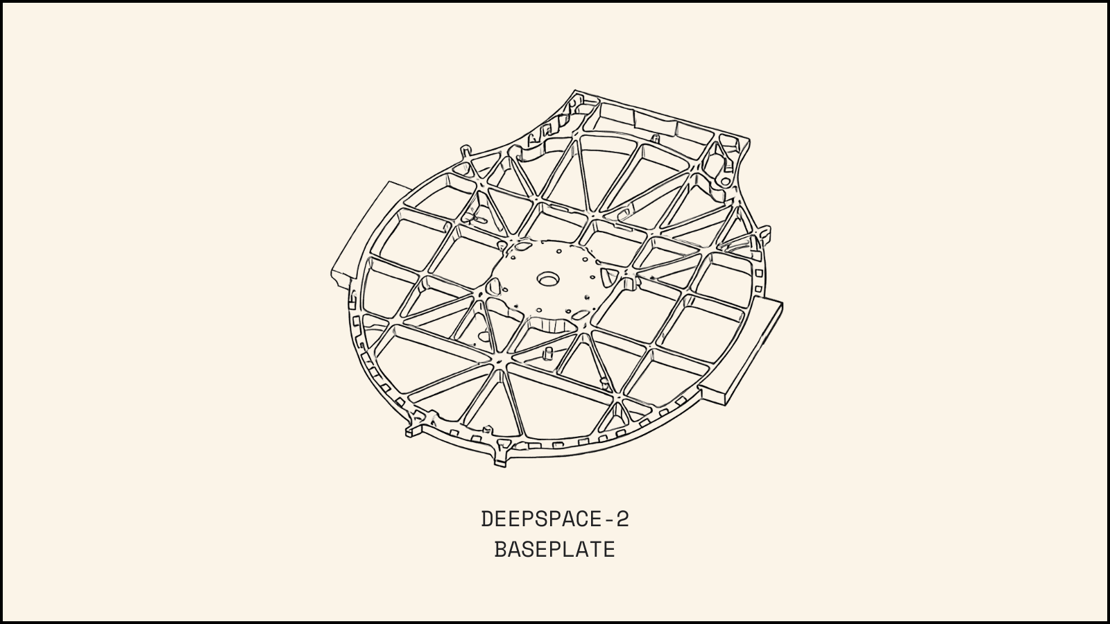
Though the primary structure consists of more than just the baseplate, the baseplate serves as the foundation through which all the forces and loads must travel before being absorbed by the rocket structure. Below is an image of DeepSpace-2's baseplate.
Some Math
The propellant tank and its contents represent the single heaviest component on the vehicle during launch. With the tank weighing 11kg and containing 60kg of Xenon gas, approximately 35% of the total vehicle mass is concentrated at the center of the baseplate (positioned above it by roughly the radius of the tank).
An additional SpaceX requirement (not listed above) specifies that all structural modes must exceed 40Hz.
A key challenge has been ensuring sufficient out-of-plane stiffness to keep the “drumhead” effect at the baseplate’s center above 40Hz.
This is governed by the following equation:
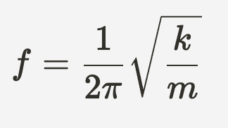
where:
f = frequency in Hertz
k = stiffness of the system
m = mass of the system
With the tank plus propellant mass fixed at 71kg, we could reduce the baseplate mass ( which partially contributes to m in the above equation). While this would help our overall mass budget, the more effective means of increasing f is by increasing k.
Though k represents system stiffness, we’re primarily concerned with the baseplate’s out-of-plane stiffness (as Xenon gas has significant mass but virtually no stiffness). To visualize this: imagine the baseplate as a trampoline with the tank/propellant mass at its center. We need to make this “trampoline” stiffer to reduce the height of each bounce (drumhead effect), while increasing the number of bounces per second. As a system’s natural frequency increases, its oscillation magnitude decreases. By raising the natural frequency above 40Hz, we’re effectively reducing the magnitude of this “bounce.”
Strength vs Stiffness
These two terms are often confused. Simply put, an object’s strength is how much force it can withstand before breaking. For example, a steel cable might support 5,000kg before breaking and dropping the suspended object. That cable’s strength rating would be 5,000kg (ignoring safety factors and OSHA guidelines).
Stiffness is a material or object’s resistance to deflection when a load is applied — important distinction there. Consider this example: if you rolled silly-putty into a noodle and positioned it with half hanging over a table’s edge, it would gradually droop and bend from gravity’s pull.
In contrast, an aluminum noodle of identical dimensions would maintain its shape without drooping. You would need to apply downward pressure on the overhanging end to make it bend toward the ground.
E vs I
In the example above, it was specified that the dimensions were identical, with material being the only difference between the two noodles.
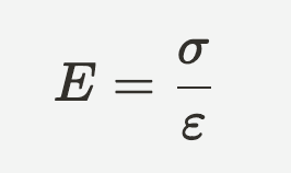
Where:
E = Young’s Modulus
σ = stress
ε = strain
Young’s Modulus is material specific. Aluminum 7075 has a different Young’s Modulus than Aluminum 6061, which differs from 316 Stainless Steel, and so on for every material.
Since we had already decided to build the baseplate from Aluminum 7075, E was fixed and no longer adjustable. That left us with I.
I represents the Area Moment of Inertia for any given 2D shape. If E represents material stiffness, then I represents geometric stiffness.
Looking again at the baseplate image, we see a central pad for tank mounting, an outer bolt circle for the CarboNIX separation system, and tall rectangular sections connecting the central pad to the outer ring. Ideally, these would be I-beams rather than rectangles, but we simplified the design for machining purposes. Given our schedule constraints, we wanted to avoid dealing with ball end mills and keyway cutters to create proper I-beams. Schedule pressure does indeed affect design complexity…
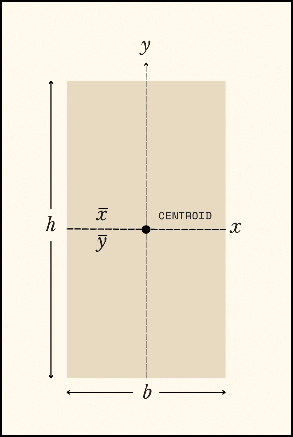
For a simple rectangle, we know that:

This equation shows that the most effective way to increase the out-of-plane stiffness of the baseplate is to increase its thickness.
Increasing the height without significantly increasing the rib thickness helps improve out-of-plane stiffness. However, this comes at a cost. As ribs grow taller while remaining thin, the likelihood of buckling increases.
This is why (if you look at the baseplate image above) numerous transverse ribs were added to interrupt the long runs of slender ribs extending from the central pad to the bolt circle where the CarboNIX ring transfers the load into the rocket.
Primary Structure Decisions
With the base structural concepts covered and the baseplate design explored, let’s take a look at some other primary structural components. The main elements of the primary structure are:
Baseplate
Radiator Panels (Side Panels, Shade Biased Panel, Top Panel)
Reaction Wheel Brackets
Tank Brackets
Avionics Box
Thruster Gimbal Brackets
At first glance, you might think one or two of these components are mislabeled, but we’ll break down each one, its design, and the types of loads it’s anticipated to experience.
Let’s start with the radiator panels. These panels make up three walls of the spacecraft and its “ceiling,” You might have questions about why we only have three walls — we’ll analyze the reasoning behind this necessary design compromise.
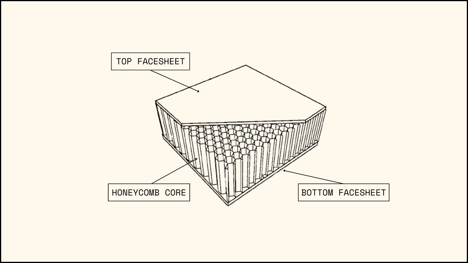
DeepSpace-2's radiator panels are constructed with Aluminum honeycomb core sandwich panels. As a review, a sandwich panel has a sparse core structure literally sandwiched between two very thin Aluminum sheets. There are many reasons for this design, but primarily it preserves a surprising amount of stiffness and strength while drastically reducing mass. For comparison, the density of Aluminum 6061 is 2.7 g/cm³ while aluminum honeycomb can have variable nominal density from 0.016 g/cm³ to 0.192 g/cm³, depending on the individual cell size and cell wall thickness.
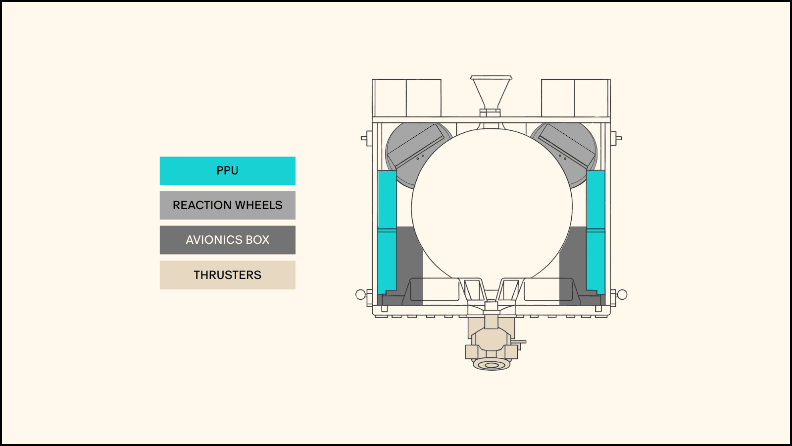
Although they serve as radiator panels for DeepSpace-2 (to be covered in the following section), these panels also function as primary structural mating surfaces for many components. The two “side panels” support Power Processing Units (PPUs), reaction wheels, solar arrays, and avionics boxes. The “shade biased panel” primarily accommodates avionics boxes and reaction wheels. The “top panel” functions as our RF deck, housing all communication and navigation equipment along with reaction wheels. It also features a bracket that holds the top of the tank laterally while allowing axial movement.
As mentioned, our strict mass limit is 200 kg — no exceptions. With nearly a third dedicated to fuel and the tank, we faced difficult decisions for other subsystems, including structures. One such decision involved the “sun biased panel”. Initially designed with four walls and a ceiling, our mass-reduction analysis revealed that the “sun biased panel” contained no essential components that couldn’t be relocated. Consequently, we eliminated it. This decision created a large opening in the spacecraft that required addressing. Our solution involves installing an MLI cover over the opening to manage line of sight issues and provides thermal insulation for the interior.
Since we can’t have unsupported radiator panels, let’s examine the brackets that secure these panels together.
Panel Brackets
The panels are connected to each other, and ultimately to the baseplate. In an effort to reduce total part count, and reduce mass we aim to have every bracket carry as much weight as possible. For example, we have brackets that hold the reaction wheels in their appropriate position and orientation. By moving these reaction wheels to the ceiling corners we were then able to use those same reaction wheel brackets as panel-to-panel brackets.
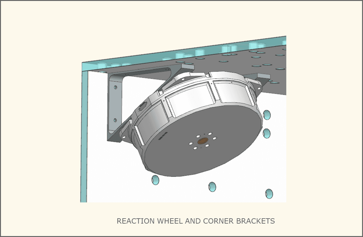
Two brackets, machined from Al 6061 are used to hold the reaction wheels in position. However they also form the corner bracket of the ceiling panel and a side radiator panel. These brackets become part of the primary structure as they not only deal with the mass and forces from the reaction wheels but also the combined forces of the various components mounted to the panels that they interface with.
In locations where we need to mechanically join the panels (radiators) to the baseplate, one solution being used is a ‘clip’ that is bonded to the panel, then bolted to the baseplate.
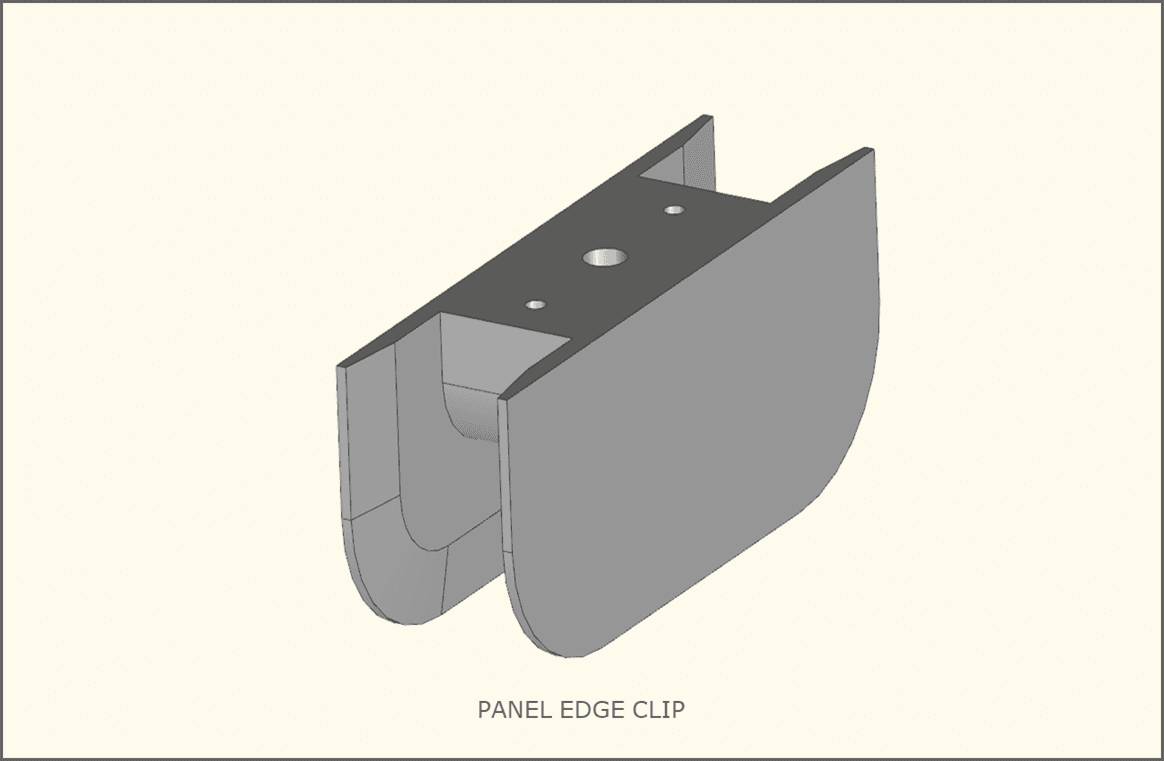
The chamfer along the edges reduces the stiffness gradient between the panel and the area of panel that the clip bonds to. The two small holes are injection / weep holes to ensure that adequate glue is present and the entire volume filled, and no voids are present in the final product. The larger hole in the underside is threaded. So there is a through hole in the baseplate and threads in the underside of the clip. The clip can now be bolted to the baseplate, securing the panel to the baseplate.
Lastly, the avionics box itself has threaded holes in its walls. This allows for fasteners to be installed from the outside, and torqued into the avionics box. At this point, the avionics box itself is also acting as a ‘bracket’ that secures and stiffens the panels on DeepSpace-2.
Structural Simulation
We’ve looked at some structural decisions that have been made but any decision requires multiple elements of verification. This includes both digital and physical testing. We will cover more physical testing in the next post but let’s explore some structural analysis foundations we employ when looking at DeepSpace-2.
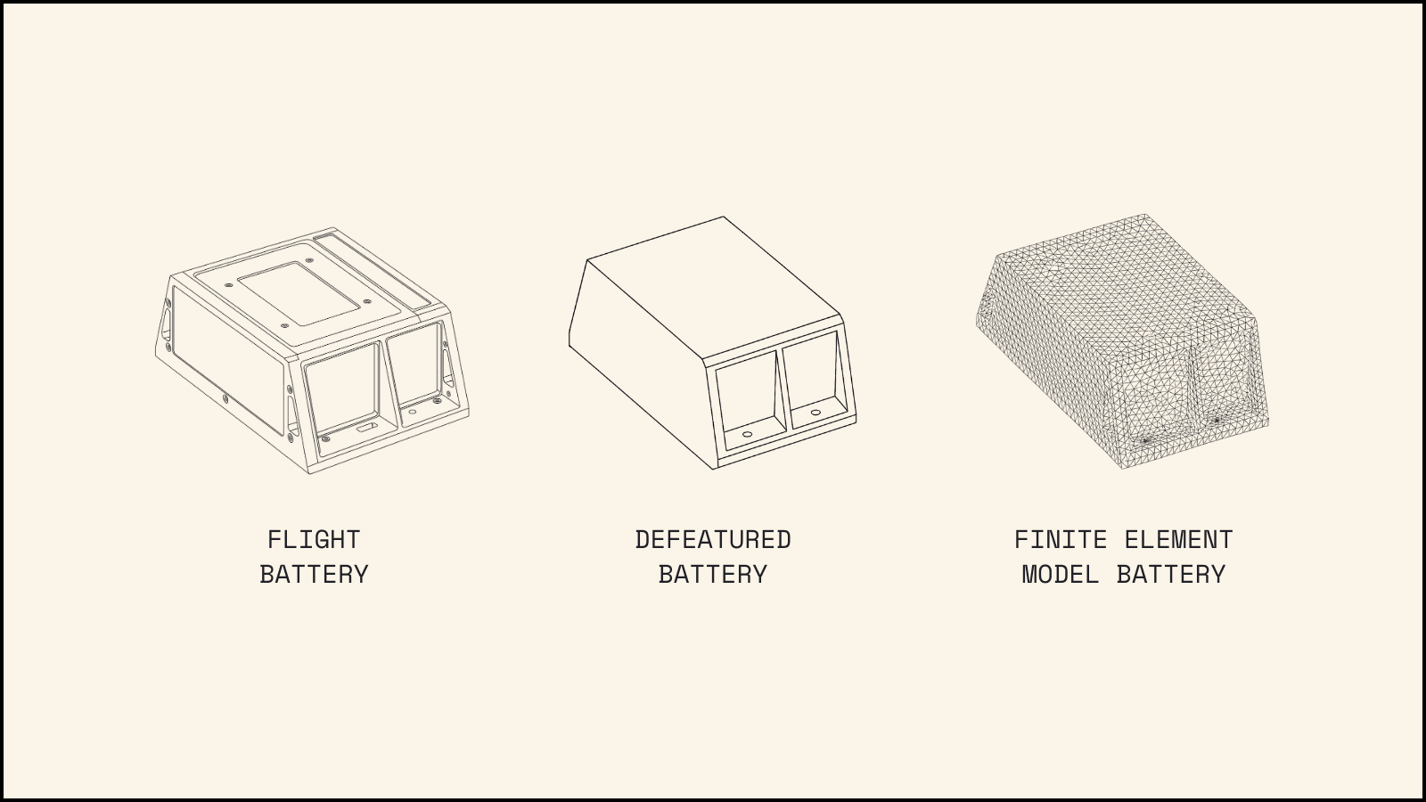
First we reduce the model to the primary structure and additional components that will effect the global model behavior. We start with just these components and then make the judgement call moving forward for the level of detail required to ensure the safety of the spacecraft. Even the components that we are including in this model go through a detail elimination progress. Through this small features such as engraved text, noncritical extrusions and cutouts, and small bolts are removed to simplify the model as seen in the battery example below.
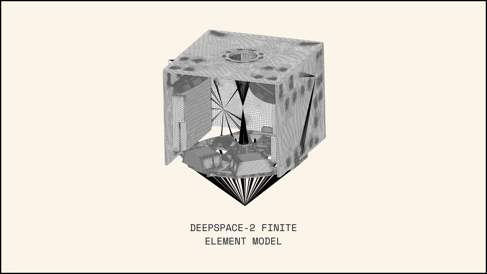
A vehicle level Finite Element Model is created. This requires different meshing and attachment techniques as there are different structure types that compromise DeepSpace-2's structural assembly. So, we may have detailed meshes representing the baseplate, structural brackets, radiator panels, etc. Those meshes must be correctly connected together to accurately represent how forces will travel through the structure. Furthermore, the entire model must them be constrained, and the forces must be applied.
We constrain the model the same way the actual hardware will be constrained, namely, via the 36 counterbored fasteners that attach to the launch vehicle via the CarboNIX ring.
While it is possible to add specific forces (with a magnitude and direction) it is also possible to subject the model to a ‘body acceleration,’ where the magnitude of the acceleration would correspond to the 12.5g lateral, and 8g axial discussed earlier in the requirements section. It is important to note that performing a body acceleration only produces accurate results if all the various masses are present in their relative CG locations. For example, even though there is no tank modeled, and certainly no 62kg of Xenon gas modeled, we can add a mass element that has a mass of 73kg, place that mass element at the tank + gas CG, and then connect that mass element to the correct bracketry in a way that is an accurate and reasonable representation in how the tank is actually attached to the tank mounts.
With this model now built, and boundary conditions now established, different analysis solutions can be run to generate stress results to know if we’re at risk of hardware breaking, and also modal results to know if we satisfy the 40Hz requirement.
We then use these results to write margins to understand how ‘close to the limit’ DeepSpace-2 may be. The goal is that we’re very close to the limit to ensure we achieve the performance we need to withstand the anticipated load cases while also minimizing overall mass - we don’t want to be any heavier than we need to be.
Thermal Bounds and Considerations
Maintaining a specific temperature range is critical for spacecraft. This is primarily due to the sensitive electronics onboard that can be damaged when they overheat. Unlike on Earth, we can’t use fans to cool them down because there’s no atmosphere in space. From physics, we know there are three primary methods of heat transfer: conduction, convection, and radiation. Let’s review these as they form essential building blocks for our discussion.
Conduction: Heat transfer through solid bodies making direct contact
Convection: Heat transfer through fluids (i.e. gasses and liquids)
Radiation: Heat transfer through electromagnetic waves
Space is a vacuum, which means there’s no convection since there’s no medium like air to dissipate heat. There’s also no conduction to the external environment since the spacecraft is floating freely. This leaves radiation as the only method for releasing heat, which is a relatively slow and inefficient process.
While you can’t conduct heat out to the environment, you can conduct heat within the spacecraft itself. If one area becomes extremely hot, attaching it to a material with good conduction properties helps spread and draw heat away — a process known as thermally sinking. Conversely, to prevent heat transfer between mechanically connected components, you can use materials with low conductance values.
The starting point for any thermal model is identifying the temperature extremes your spacecraft will experience — the “hot case” and “cold case.” When setting these boundaries, we must first consider environmental factors.
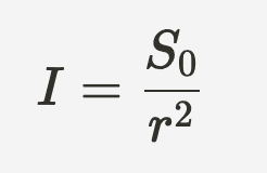
DeepSpace-2 is expected to travel 0.1 AU away from Earth. Since a target asteroid hasn't yet been selected, the spacecraft may be as close as 0.9 AU or as far as 1.1 AU from the sun. Solar radiation bombards the spacecraft with photons that are absorbed as heat. The amount of radiation reaching the spacecraft follows the inverse square law:
where:
I = solar radiation intensity (W/m²)
S₀ = solar intensity at 1 AU = 1361 W/m²
r = the distance from the Sun (m)
This means the total heat entering the spacecraft at 0.9 AU and 1.1 AU calculates to:
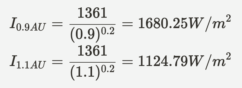
Let’s assign the solar radiation intensity at 0.9 AU to the “hot case” and that at 1.1 AU to the “cold case.” As DeepSpace-2 is a deep space spacecraft, we don’t need to worry about eclipse conditions creating the cold bound, since we won’t spend time orbiting in Earth’s shadow.
However, determining the hot and cold cases involves more than just environmental factors. We also need to consider DeepSpace-2's operational modes. In the spacecraft power 101 class, we defined 4 modes with the following power generation:
Minimum Power Mode = 36 W
Safe Mode = 258 W
Earth Communication Mode = 345 W
Burn Mode = 1432 W
According to the First Law of Thermodynamics, energy cannot be created or destroyed. This power becomes a heat source within our structure, indicating the most and least heat-generating modes. Therefore, we’ll assign Minimum Power Mode to the “cold case” and Burn Mode to the “hot case”
So in total:
Cold Case | Hot Case | |
|---|---|---|
Distance | 0.9 AU | 1.1 AU |
Mode | Minimum Power Mode | Burn Mode |
Now let’s examine how we ensure our spacecraft components remain within safe temperature ranges, given the hot and cold case scenarios.
First, we need to define a safe temperature range. This is primarily determined by the operational limits of our electrical components, which can be found in their documentation. It's important to build in safety margins rather than operating at the absolute limits. These values will be further refined during thermal modeling. For our spacecraft, let's establish operational bounds of 0°C to 60°C. Our goal is to keep the “cold case” temperature above 0°C and the “hot case” temperature below 60°C.
To calculate the simplified thermal balance of a spacecraft, we must account for all heat entering and leaving the spacecraft. This relationship is described by the Stefan-Boltzmann Law
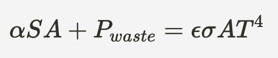
where:
α =absorptivity of the surface
S = solar flux (W/m²)
P = total power radiated (W)
ε = emissivity of the surface
σ = Stefan-Boltzmann Constant = 5.67x10 ⁻ ⁸ W/m²K⁴
A = radiative surface area (m²)
T = temperature (K)
Let’s play around with some numbers. For now, let’s assume a surface area of 1 m². For spacecraft, we want high emissivity values, which allow us to radiate energy more effectively. We also want low absorptivity values to minimize heat entering the system. A “blackbody” absorbs all incident radiation and emits it all back out so, having a value of 1 for both properties. For our craft, let’s set an emissivity value of 0.9 and an absorptivity value of 0.1.
Now, let’s calculate simplified temperatures for both hot and cold cases using these values
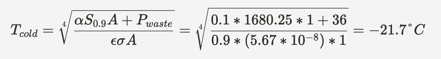
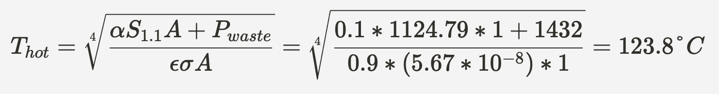
As we can see, our spacecraft is not within the required temperature bounds on either end. Fortunately, there are solutions available!
For the cold case, we can add patch heaters in critical areas. We should prioritize installing these heaters around temperature-sensitive components like batteries, feed lines, and electronics. With strategic placement of enough patch heaters, we can bring the lower temperature bound within our target range.
For the hot case, the solution isn’t as straightforward. Recall that we sized our radiative surface area to 1 m². Let’s explore this further by rearranging our equation to specify our desired temperature and solve for the required area instead.
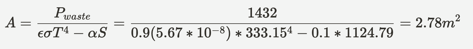
This gives us a target radiator area of 2.78m². However, this creates a moving target because increasing our radiator area makes the cold case even colder. The values constantly shift when we adjust factors like surface coatings (changing emissivity or absorptivity values), travel bounds, or heat generation. Consequently, we must constantly update our calculations to maintain our target temperature range.
Now that we’ve established a simplified approach to estimating radiator area, let’s consider another factor.
Our simplified model assumes the spacecraft maintains a uniform temperature throughout its body, which couldn’t be further from reality. Let’s examine heat density distribution to identify our primary heat sources.
During burn mode, we fire our thrusters to transit to our target, creating an extreme heat source. Fortunately, we only fire one thruster at a time. This means only one of our two PPUs draws high power for its respective thruster. Additionally, both avionics boxes operate simultaneously, though one typically draws significantly higher power than the other in this mode. Finally, all four reaction wheels run to control the spacecraft’s trajectory. While other subsystems and smaller components operate during this period, these four components represent the largest heat sources that need to be addressed during burn mode.
Let’s now examine the materials we plan to use on DeepSpace-2 and their thermal significance. Earlier, we discussed thermally conductive and non-conductive materials, which is one of the most critical factors. These materials allow us to either spread heat equally in thermally conductive zones or limit heat transfer in thermally isolated zones.
When selecting a high conductance material, we typically choose metals like aluminum, copper, or silver. For thermal isolation, we use materials such as Glass Fiber Reinforced Polymers (GFRP), PEEK, Teflon, and Multi-Layer Insulation (MLI).
MLI is a particularly effective insulating material composed of alternating layers of thin reflective material (like Kapton or Mylar) and spacing material. The reflective layers bounce back infrared radiation, while the spacing material has low conductivity, providing enhanced thermal isolation between layers. Each reflective layer conducts heat well within itself and equalizes quickly, but minimal heat transfers across the depth of the material. This creates a highly effective solution for isolated thermal zones and reduces temperature fluctuations. Due to these properties, MLI is commonly used around thermally sensitive equipment. It also offers the significant advantage of being extremely lightweight, helping us stay within our limited mass allowance.
Summary
Spacecraft mechanical design requires a comprehensive approach balancing numerous constraints. Engineers must create structures strong enough to withstand the extreme vibration experienced as part of launch while minimizing mass to meet strict weight limitations. Material selection is critical, with considerations for thermal properties, structural integrity, and radiation resistance. All these factors must be addressed while adhering to the mission's specific requirements, budget constraints, and qualification testing parameters.
Stay tuned for a deep dive into the details of solar array structural design, which will be posted in 2 weeks.