Spacecraft Radio Communications
Matt Gialich
Let's talk spacecraft radios! I'm going to walk you through how we communicate with our spacecraft when they're millions of miles away. We've built two spacecraft so far, Odin and DeepSpace-2, and the radio systems on these two couldn't be more different.
Odin was our first mission, built under a super tight timeline. Its radio system was basically pieced together with what we could get our hands on quickly. It had low power, could only transmit in one direction at a time, and we couldn't even be sure which antenna was active at any given moment! Think of it like trying to have a conversation while holding a megaphone that keeps randomly pointing in different directions.
DeepSpace-2, on the other hand, is our second mission and benefits from everything we learned from Odin's challenges. We've given it much more powerful transmitters (5-9 times stronger!), it can listen and talk in multiple directions simultaneously, and we always know exactly how it's configured. It's like upgrading from a walkie-talkie to a modern smartphone with multiple antennas.
Throughout this document, we'll dive into the details of space communications, including link budgets (how we calculate if a signal will make it across millions of miles), data transmission protocols (how we package information), and antenna designs (how we physically send and receive signals). By comparing the two missions side by side, you'll see how our approach has evolved and why certain design decisions make all the difference when communicating across the vastness of space.
Link Budget
Selecting radios starts with determining what kind of radio signal will meet the mission’s communication requirements. This process is called link design, and it is summarized in a link budget. There is a separate link budget for getting commands to the spacecraft - we call this path the "uplink" - and for getting data back to Earth -"downlink" - and designing the link can get complicated. At a high level, the link design is broken down into three stages: (1) effective transmitter power, (2) channel losses, and (3) receiver capability. We can quantify each stage and combine them to figure out if a particular radio frequency (RF) link will work. For simplicity, we will skip the topic of frequency selection and focus on the frequency we used for Odin and are currently using for DeepSpace-2.
In general, the power gains and losses between stages of the link budget are represented as successive multiplications and divisions. By convention, engineers convert these values to decibels (dB) to make the link budget a matter of addition and subtraction. We’ll present all measurements in decibels here - if you want more info on the conversion process, you can look it up separately. Now, let’s compare the Odin and DeepSpace-2 link budgets and explain the relevant terms.
Raw Power
Downlink @ 12 million miles | Odin | DeepSpace-2 |
|---|---|---|
Effective Transmit Power (dB Watts) | 8 | 16 |
Channel Losses (dB) | -251.2 | -251.2 |
Receiver Capability (dB) | 39.3 | 39.3 |
Received Power (sum above three, dB Watts) | -203.9 | -195.9 |
The receiver capability is the same because we are using the same 85-foot-wide ground antenna to pick up the signals on Earth — we require some large antennas to operate in deep space. The low-noise amplifier near the antenna feed has the second most significant impact after antenna size. To achieve optimal performance, the most sensitive ground stations cool these amplifiers to cryogenic temperatures (below -80 C or -100 F).
The channel loss is primarily due to the free space loss of -245 dB required to send the signal over 12 million miles. Pointing loss is another significant factor, as this budget accounts for imperfect spacecraft alignment with Earth. The budget also includes polarization mismatch and atmospheric losses, though these contribute much less to the overall loss.
The big difference is in the 16 dB Watts that the DeepSpace-2 spacecraft delivers in effective power, which is over 6 times the effective power output of Odin. This effective transmitter power is referred to as Effective Isotropic Radiated Power (EIRP). We’ll discuss the differences in detail, but this term encompasses the power amplifiers, antennas, and losses from spacecraft components such as cables, switches, and splitters.
Adding more power amplification is a simple way to increase the effective power, although this requires the spacecraft to generate sufficient electrical power and dissipate the resulting heat. There are two primary amplifier technologies: traveling wave tube amplifiers (TWTA) are more robust and efficient, but also tend to be expensive and have long lead times. These are usually used for very-high-power applications, so there are less built in the range that a small non-telecommunication spacecraft needs. Modern small spacecraft usually work with solid state power amplifiers (SSPA): these have significantly improved in reliability and performance over recent decades, but their primary advantages are low cost, low mass, and ready availability.
Spacecraft traditionally use the largest possible antenna to maximize effective power. For example, Voyager uses a 12-foot antenna, while closer missions like Psyche (headed to the asteroid belt) use a 6.5-foot antenna. The primary advantage of a larger antenna is that it can boost communication in both directions — improving uplink signals to the spacecraft and downlink signals back to Earth. However, these antennas can be heavy and require that the antenna be pointed very accurately at Earth. While this is straightforward during normal operations, it becomes problematic if the spacecraft malfunctions.
In order to address this vulnerability and assist with early spacecraft operations near Earth, most deep space vehicles also incorporate hemispherical antennas. These smaller antennas provide much less gain but feature very wide beams. By combining these antennas, a spacecraft can achieve a near-omnidirectional radiation pattern, enabling Earth communication regardless of spacecraft orientation. Though some signal “nulls” (uncovered areas) exist, careful antenna design and operational planning can minimize their impact.
The received power (sum) of this link budget determines what kind of devices we need at the ground station. While amplifiers are used to boost the signal to detectable levels for the ground radio, they unavoidably amplify background noise as well — creating an inevitable tradeoff in signal processing.
What about the bits?
Radio signals carry information digitally encoded as bits. Simply detecting the signal - the raw power transmitted or the "carrier” - isn’t sufficient; we must be able to decode the data carried on that signal.
Determining our ability to decode the signal requires an additional part of the link budget and is captured in a ratio called Eb/N0 (”Ebb-No”). Eb/N0 is the RF energy in one bit of data compared to the average power of background noise. If Eb/N0 is too low, it becomes impossible to distinguish actual data from random noise. To calculate this value, we first normalize the received power mentioned above, resulting in a unit of dBc/Hz that we won’t dive into here. We then add terms for the data rate and the encoding.
Link @ 12 million miles | Odin | DeepSpace-2 |
|---|---|---|
Received Power Ratio (dBc/Hz) | 24.7 | 32.7 |
Data Rate Effect (dB) | -33 | -20 |
Coding Gain (dB) | 7.4 | 6.1 |
Eb/N0 (dB) | -0.9 | 18.8 |
Trying to send data faster means that each bit occupies less time on the radio wave, containing less energy and making it harder to receive accurately. This challenge is reflected in the data rate effect above. While a lower data rate improves reception reliability, it also takes longer to transmit the same amount of information.
To understand coding gain, we need to examine how bits are encoded on radio signals — a process called modulation. You may be familiar with AM and FM radio, which stands for “Amplitude Modulation” and “Frequency Modulation” - these are methods for placing data on radio waves. We’re interested in digital data, so here’s an example to consider: imagine I am sending you a signal on a 1 MHz wave (1,000,000 cycles per second). One way I could distinguish a “0” bit from a “1” bit is by slightly shifting the frequency — perhaps 1.00 MHz represents “0” and 1.01 MHz represents “1”. As the receiver, you’d determine whether it’s a 0 or a 1 by measuring the frequency. Then, as the sender, I would shift (or "key") the frequency every millisecond (1,000 times per second) between these two values. This frequency modulation achieves a data rate of 1,000 bits per second (bps) using two “symbols” (1.00 MHz and 1.01 MHz). The data rate is determined by how quickly I switch between modulation symbols. Many space missions use phase changes rather than frequency shifts — known as phase shift keying (PSK). Various combinations of modulation type, modulation order (number of symbols), frequency, and data rate offer different performance characteristics — we’ll leave that for you to take in a college course if you want to dive into it. For Odin and DeepSpace-2, we use a two-symbol (binary) modulation where bits and symbols are equivalent.
Since modulation is changing a physical property of the radio wave, the receiver has to detect that change to receive the data. If the signal is really weak or there is interference, the receiver might misinterpret bits — believing a “0” was sent when it was actually a “1”, or vice versa. We call this a bit error. This brings us back to Eb/N0: higher values mean we can more accurately read bits on the radio wave, reducing the likelihood of bit errors. There are theories and measurements for what Eb/N0 we need to decode a signal at a given bit error rate. For example, with binary phase shift keyed modulation and a bit error rate less than 1e-5 (one error per 100,000 bits), we need an Eb/N0 of at least 9.6 dB — meaning the energy in each bit must be 9.1 times stronger than the noise.
We can improve our chances of getting a good signal by adding a forward error correction (FEC), also called encoding. This technique allows the receiver to detect and correct bit errors. It’s “forward” because the sender doesn’t need any information from the receiver, making it ideal for one-way or long-distance links. However, every FEC requires transmitting additional bits, creating a trade-off between extra data volume and improved signal reception. The benefit of encoding is measured as coding gain, also expressed in decibels. The coding gains in the table above (6-8 dB) improve reception as effectively as increasing power by 4x to 7x, making encoding a highly efficient performance enhancement tool. FECs aren’t limited to radio communications — they’re also used in computer memory and disk operations. We’ll discuss FEC and encoding in more detail below, as it pertains to Odin and DeepSpace-2, but you can see from the table above that the coding gains differ because the vehicles use different encoding schemes.
There are lots of variations of FECs, but the common ones used for spacecraft are split into two categories: block codes and convolutional codes. Block codes are very efficient but require a fixed number of bits to operate on. These tend to be better for handling bursts of noise that corrupt multiple bits in a row, but they require processing the entire block for decoding, making partial blocks difficult to interpret. Bose–Chaudhuri–Hocquenghem (BCH) and Reed-Soloman (RS) are two widely used block code families in space communications. Convolutional codes — ranging from simple convolutions to more sophisticated turbo codes — process data streams continuously, so they tend to keep their correction bits close to the data bits they protect. This approach simplifies decoding of smaller data segments but increases vulnerability to burst errors. Various hybrid codes and techniques exist to address these limitations, but they are more complex to implement.
Comparing Odin and DeepSpace-2's Eb/N0 values above reveals that under these link conditions, DeepSpace-2 can be successfully decoded (exceeding the required 9.6 dB) while Odin cannot. Unlike with raw power reception, adding ground station amplifiers does not improve Eb/N0. This means that while we might detect Odin’s carrier signal at this distance, extracting usable data would be virtually impossible. We recognized this limitation during design — at great distances from Earth, Odin would need its directional antenna precisely aimed at Earth in order to transmit a signal. Consequently, if Odin entered safe mode far from Earth, recovery would be impossible until it returned to closer range, which was scheduled to occur several months into the mission. DeepSpace-2, by contrast, was designed specifically to maintain communications even when not directly pointed at Earth.
The spacecraft radio must support the frequency, modulation, bit rate, and encoding specified in the link design. The availability, cost, and lead time of commercial radios directly influences link design decisions. This relationship is best illustrated by comparing the radio selections for Odin and DeepSpace-2.
Spacecraft Radios
Spacecraft radios are a critical component in our mission design. We decided early on to purchase radios rather than develop them in-house. With DeepSpace-2, we had sufficient time to evaluate multiple options. For Odin, however, time constraints limited us to the Vulcan radio as our only viable option.
To be clear: the Odin radio performed as expected. We successfully received data from it multiple times throughout the mission. Vulcan Wireless delivered a product that met our expectations.
Our radio system needed to satisfy three key requirements. First, due to RF licensing restrictions, we were limited to the experimental deep space portions of S or X band. Since no X-band radios could meet our delivery timeline, we needed a radio that could both send and receive on S-Band (~2GHz) or else it was a non-starter.
Second, we needed the radio to determine the spacecraft’s position in space. This capability is provided through “ranging” — a process using pseudorandom code to measure signal time-of-flight, which tells us the spacecraft’s distance from Earth. We also required “coherent turnaround” functionality to measure range rate, allowing us to calculate velocity.
Third, we prioritized radiation testing and, ideally, flight heritage in the cislunar space or beyond. While we could have conducted our own risk assessment or radiation testing, both the Vulcan radio (used on Odin) and RocketLab's Frontier radio (selected for DeepSpace-2) already had proven flight heritage.
Odin
Odin’s radio was a transceiver (handling both transmission and reception) provided by Vulcan. The radio was great and performed as advertised. We owe a lot of credit to the Vulcan team who delivered it on a timeline no one else could — this was our primary selection criterion.
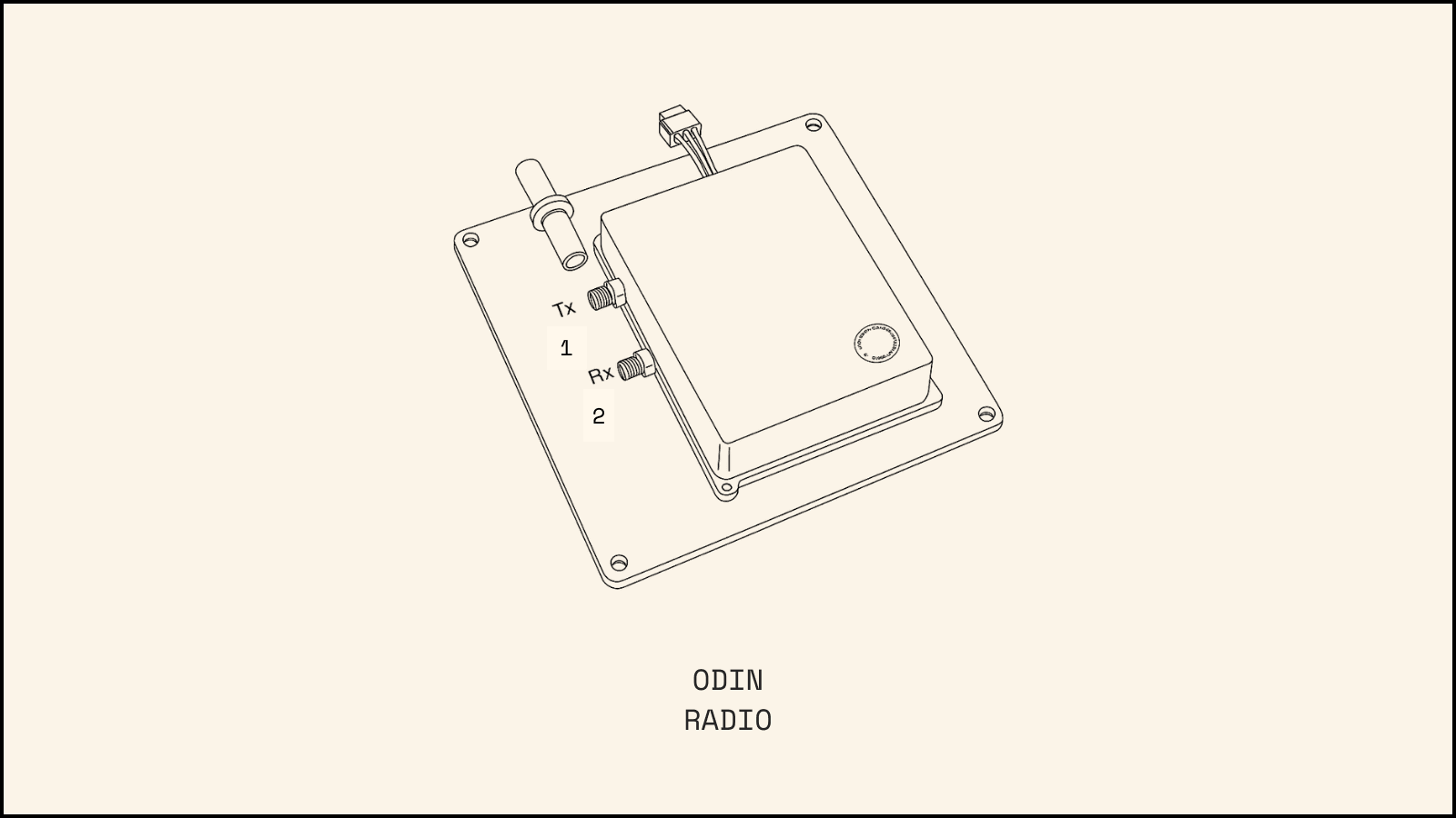
We accepted certain risks since the Vulcan wasn’t specifically designed for our application. It came as a fully integrated unit with both amplifiers and diplexer in a single package. The diplexer allows uplink and downlink signals to share the same coaxial cable and antenna. While this integrated design aided integration and reduced mass, we didn’t anticipate the significant drawbacks it would create.
The integrated configuration severely limited our ability to modify the RF chain. Adding an amplifier to either the uplink or downlink would have required heavy, power-hungry switching and combining chains to manage multiple signal paths while preventing self-interference. Adding another transmit amplifier would have meant running the integrated 4W amplifier at a lower setting — effectively wasting mass. This is because the affordable solid state amplifiers we surveyed required input power below 1W. Any attempt to enhance the RF chain would have exceeded Odin’s tight mass and power budgets.
The integrated diplexer also restricted our antenna options, which we’ll discuss in a separate section.
Data rate was another critical consideration. Your ability to receive a signal on the ground is proportional to the data rate. For context, Voyager — the most distant spacecraft from Earth — currently transmits data back to Earth at 160 bits-per-second. Keep in mind that Voyager uses a traveling wave tube amplifier (TWTA), which offers higher gain through greater mass, and a directional antenna. In contrast, Odin had just 4W of output power with a solid state amplifier and patch antennas, so we needed the lowest possible data rate to compensate.
The Vulcan radio was advertised to support data rates as low as 1,000 bits-per-second (1kbps), which we used in all our link budgets. This proved to be a mistake. While the radio could technically operate at 1kbps, the noise parameters at this rate were suboptimal. In fact, our testing revealed that the radio actually performed better at 2kbps. This serves as an important reminder of how complex radios are. And when you're in deep-space, where the margins are razor thin, there’s virtually no room for error.
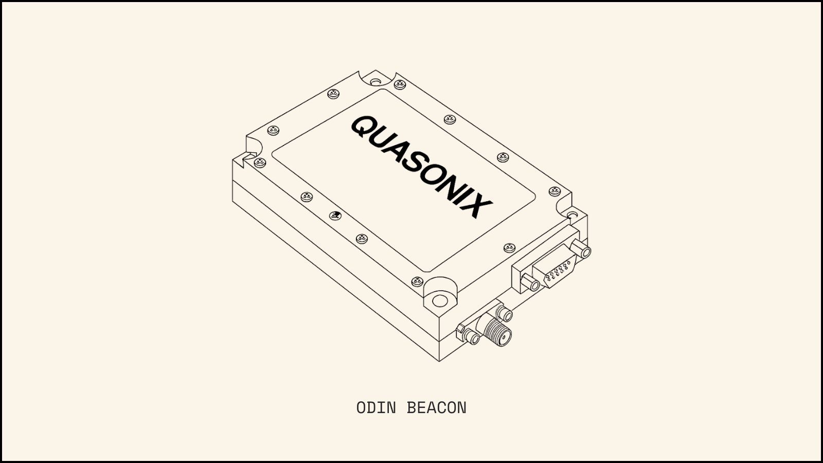
Odin also carried a beacon made by Quasonix. We included this to make sure that we could receive periodic signals from the spacecraft at set intervals. We initially planned to receive data from the radio sent back to Earth, but a manufacturing error in the flight computer prevented data transmission. Given our time constraints, we repurposed this as a beacon that would transmit a signal every 8 hours, ensuring we could at least track Odin’s location in worst-case scenarios. The beacon had higher power but more limited directionality than the Vulcan radio, so there is a chance it might have worked without us detecting it. Other issues affecting Odin may also have prevented the beacon from functioning as expected.
DeepSpace-2
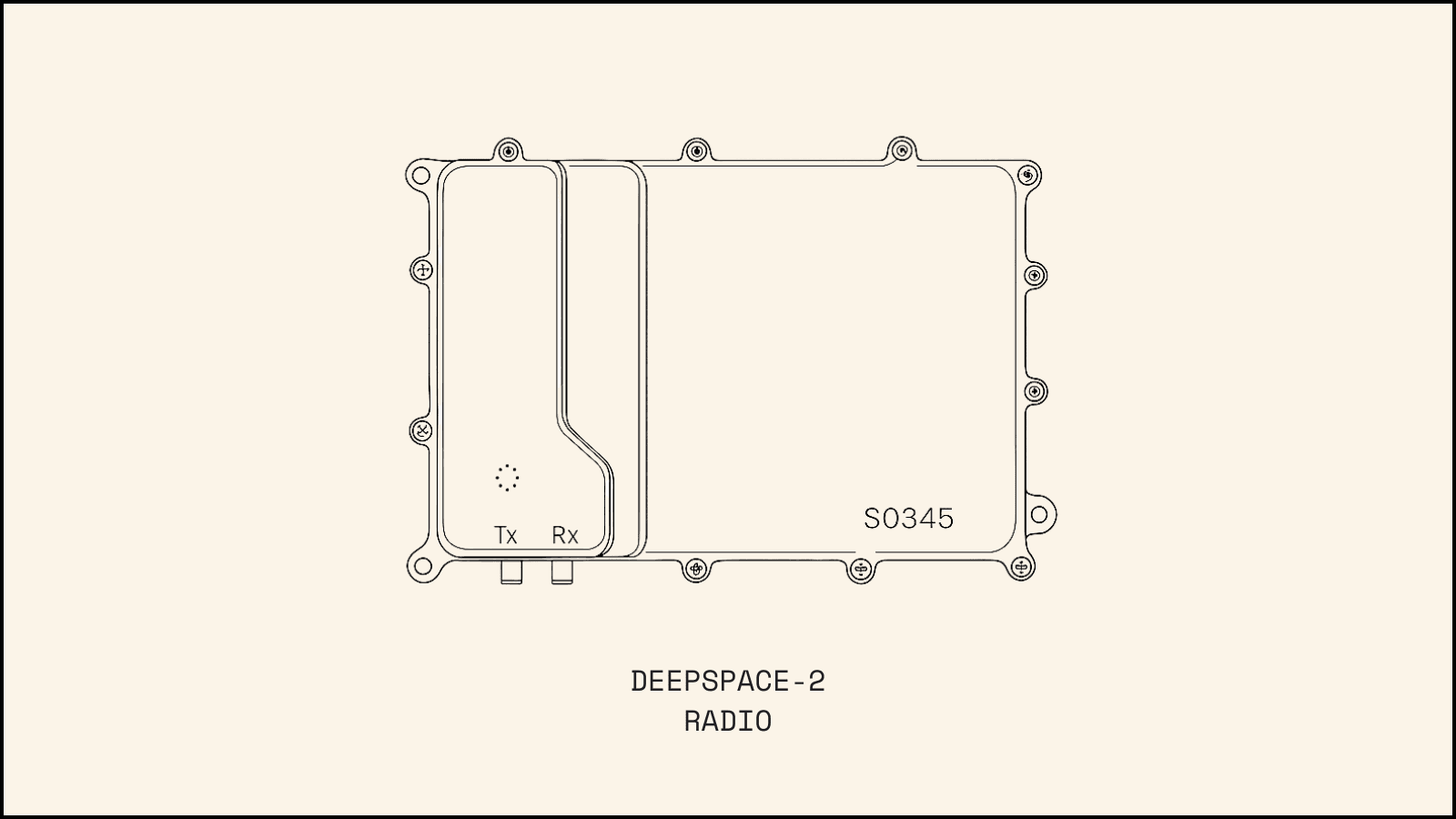
For DeepSpace-2, we had considerably more time and knowledge about building radio systems for deep space. We carefully evaluated numerous radio suppliers that could meet our requirements, ultimately selecting the RocketLab Frontier radio. This radio is also a transceiver but offers key advantages: it lacks integrated power amplifiers and features separate transmit and receive ports. The technology for this radio was licensed from Johns Hopkins University, where it was used on the Parker Solar Probe. We required an S-band variant since the Parker Solar Probe used X-band. This version of the radio was successfully flown to the moon in 2022.
We also made a crucial decision regarding which component of the spacecraft would control the radio. On Odin, the radio connected directly to our flight computer, which consumes a lot of power, as you may remember from our previous write-up. This means that, if something goes wrong or our thermal mapping is off, we risk losing communication entirely. Additionally, while the flight computer underwent radiation testing, it lacked long-term flight heritage. Therefore, we implemented a radiation hardened Microchip microprocessor that serves as a bridge between the spacecraft and radio while managing the entire power system. If all other systems fail, this processor will maintain the spacecraft’s ability to receive commands and send critical avionics data using less than 1W of total power, compared to the 60W required by the flight computer.
Now, here is where lessons from past experiences really proved their value in our radio selection. Though not advertised, the Frontier radio can transmit at rates as low as 100 bits-per-second —even lower than Voyager. Combined with our external antenna capabilities, this dramatically increased our link margin. Rather than immediately designing our system around this 100bps capability, we decided it would be better to use the advertised value of 1.6kbps for all link budget calculations until we could conduct proper testing. This past week, we finished our first end-to-end radio test, and it revealed very similar results to what we experienced with the Vulcan: while the radio can indeed operate at 100bps, the noise levels match those at 400bps. Even with this limitation, we still achieved a fourfold increase in margin. By planning ahead, we avoided having to make any last-minute spacecraft modifications.
The Frontier radio also offers approximately 20 dB greater sensitivity in signal acquisition and lock. This improvement comes primarily from its advanced signal detection algorithm, though we’re still conducting tests to verify the advertised sensitivity. This enhanced sensitivity allows us to send commands to the spacecraft at much greater distances, covering the entire DeepSpace-2 flight envelope. The increased sensitivity also enables us to use smaller ground antennas, particularly during early mission phases, providing us significant flexibility in securing ground antenna time.
Antennas
When selecting antennas, we faced a fundamental decision: should we use directional or omnidirectional antennas? Most deep-space missions avoid this trade-off by implementing both types. The Psyche mission, for instance, carries both a high-gain directional antenna and a low-gain omnidirectional antenna.
Why use both? Well, as our link budget and data rate calculations demonstrate, a high-gain antenna provides the most efficient way to transmit more data back to Earth. However, these antennas are expensive and add substantial mass to the vehicle, so for our craft, we ultimately decided to use only omnidirectional low-gain antennas.
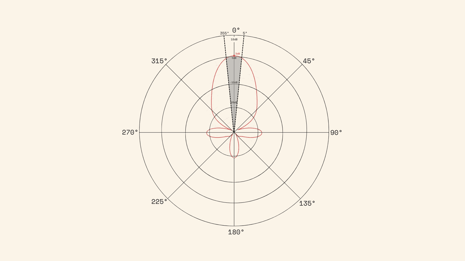
To the untrained eye, understanding antennas can be difficult. For simplicity’s sake, we’ll stick to presenting antenna data using two-dimensional plots with logarithmic scales, so keep in mind that a 3dB drop represents an approximately 50% loss of total power. Here's an example of an antenna pattern:
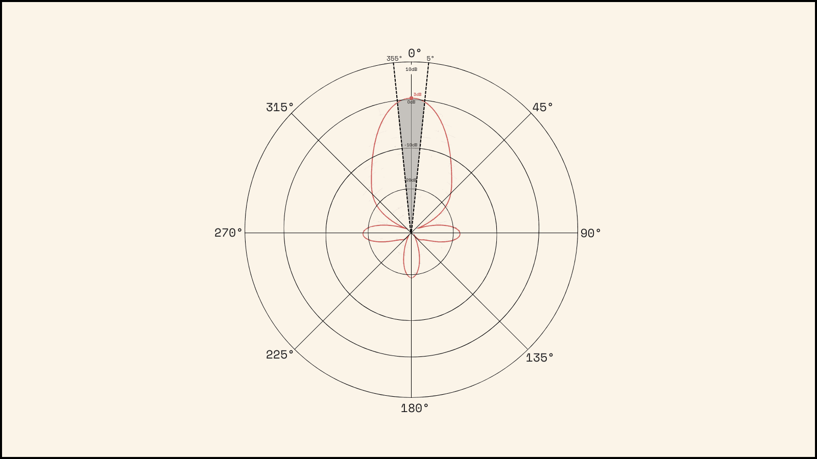
There are a few things to note about this pattern. The first is that the antenna’s strength or "gain" varies with the look angle. On the polar plot, distance from the centerpoint represents signal gain in dB, while clockwise rotation corresponds to increasing "look angle". A look angle of zero degrees would mean that the receiver is directly in front of the transmitting antenna. For example, at a look angle of 2.5 degrees, this antenna has a gain of 2 dB, while at 30 degrees, the signal has a gain of -10 dB.
An important metric for any antenna is the "boresight gain" — the maximum gain of the antenna, conventionally aligned with 0 degrees, or the "boresight" angle. In our example above, the boresight gain is 3 dB. This means that at boresight, an incoming wave with 50 dBm (100 Watts) of energy would be received as if it had 53 dBm (200 Watts) of energy!
As we rotate along the circle, away from the boresight angle, we reach a point at 5 degrees where the gain drops to 0 dB - 3dB below our boresight gain. This is called the "half power angle", because a 3dB drop is roughly equal to losing 50% of the total antenna gain . At this look angle, our 50 dBm (100 W) signal would be received as if it was a 50 dBm (100 W) signal. The "half power beam width" (HPBW) is equal to the sum of the half power angles in either direction, which is just 2 times the one-sided half power angle for most antennas. The half power beam width is another critical figure of merit for comparing antennas. As an example, for this antenna, the half power beam width would be 10 degrees. Anywhere within the half power beam width, our 50 dBm (100 W) signal would register as 50 dBm (100 W) or higher.
As we continue to rotate away from boresight, we reach a point at about 60 degrees where our gain is very low -- negative 27 dB. At this point, our 50 dBm (100 W) signal incoming to the antenna would be received as if it had a strength of 23 dBm (0.2 W). This is called a null, and is one of the worst possible look angles. If DeepSpace-2 were to point a null at the Earth, the two would almost certainly be unable to hear each other. Fortunately, the nulls make up a very small fraction of the beam pattern.
Finally, as we reach 90 degrees away from boresight, we reach the first sidelobe of the antenna. In our use case, the sidelobes represent unwanted power leakage, as when we point the antenna boresight toward the Earth, the sidelobes will radiate power away into space. A major problem for many antenna designers is sidelobe minimization.
Odin
Odin used Printech high-gain and Vulcan hemispherical antennas, each handling both transmit and receive functions. Due to our tight selection timeline, our options were limited. Using combined antennas offered advantages in weight reduction (one antenna weighs less than two) and simplified mounting requirements, as we only had a single mounting point to worry about.
However, these combined antennas came with significant tradeoffs in beam pattern and gain.
A major drawback was that transmit and receive polarization had to be identical on each antenna. This is unusual in spacecraft design, as different polarizations typically provide better isolation between antennas (preventing the satellite’s receive antenna from detecting signals from its own transmit antenna). Additionally, this configuration limited the number of ground station options — if a provider's polarized antenna became unavailable, we couldn't use that antenna or its associated satellite transmit chain.
Another issue we faced is the antenna noise figure (another figure of merit for the receiver system) was degraded as a result of using the same antenna for transmit and receive. While we won't go into too much detail on noise figure, it is a parameter we would like to be as small as possible (closely related to the N0 component of the Eb/N0 ratio). The transmitting antennas heat up during operation, which normally wouldn’t affect separate receive antennas. in temperature while sending energy into space, which is an irrelevant change for separate transmit and receive antennas. However, since we used the same antenna for both functions, the hot antenna appears as an increase in thermal noise figure when looked at from the receive chain.
DeepSpace-2
For DeepSpace-2, we had the luxury of time. This allowed us to select a radio that required designing our own RF subsystem, giving us freedom to choose exactly the antennas we wanted.
We selected only omnidirectional antennas — specifically a combination of hemispherical antennas
Without the combined transmit/receive limitations, DeepSpace-2 has significantly better-performing antennas
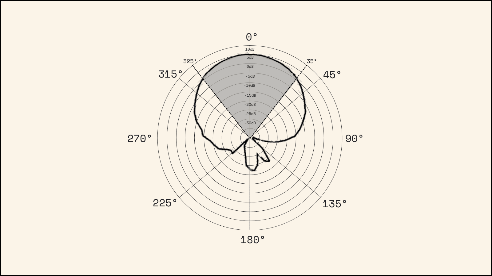
DeepSpace-2's antenna system was designed with worst-case communication scenarios in mind. There are two sets of receive antennas, each set containing a pair facing opposite directions, similar to Odin. Unlike Odin, however, both pairs of receive antennas are hemispherical with a greater half power beam width — approximately 100 degrees each — without sacrificing boresight gain, which totals about 6dB for DeepSpace-2.
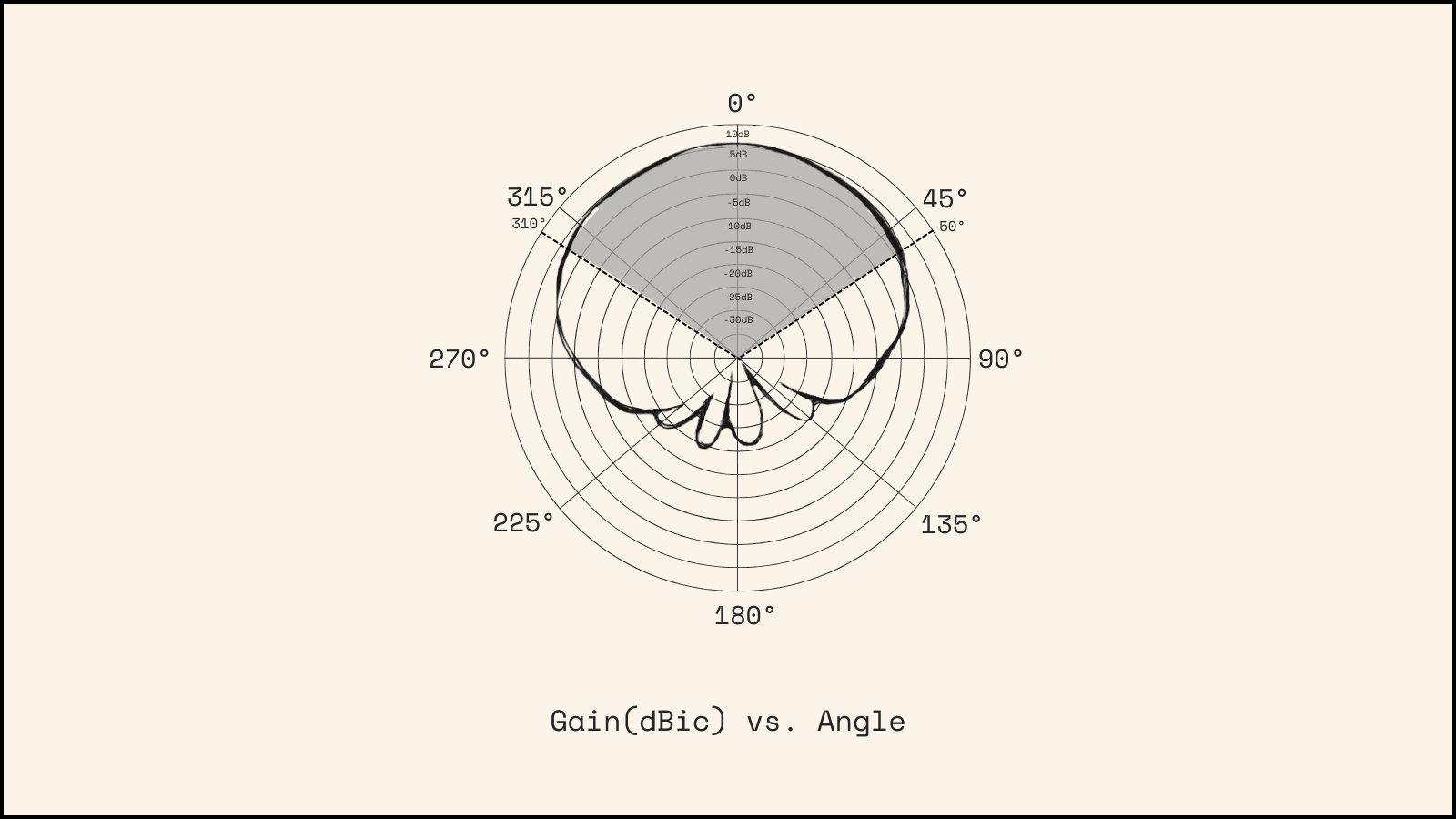
The transmit chain similarly consists of two pairs of opposite-pointing hemispherical antennas. Typically, satellite projects employ one set of hemispherical, low-power command and health antennas, and one set of highly-directional, high-power image and payload antennas. In our case, we prioritized reliability over potential deep-space performance gains. We designed the transmit chain to improve our chances of receiving data even in anomalous circumstances at the edge of our operational distance.
Data packets
RF data, like many other protocols, are organized into “frames” — blocks of data that follow a specified format with elements such as header and size. This structure allows receivers to identify what to look for when reading data and enables standardization of many aspects of communication such as Forward Error Correction (FEC) codes. Many of these standards are established and published by the Consultative Committee for Space Data Systems (CCSDS).
Odin
The Vulcan radio offered no control over RF framing. We could only input data, while the radio automatically handled framing, randomization, and FEC application. By carefully adjusting timing and data size, we typically achieved one space packet per frame, though this wasn’t guaranteed.
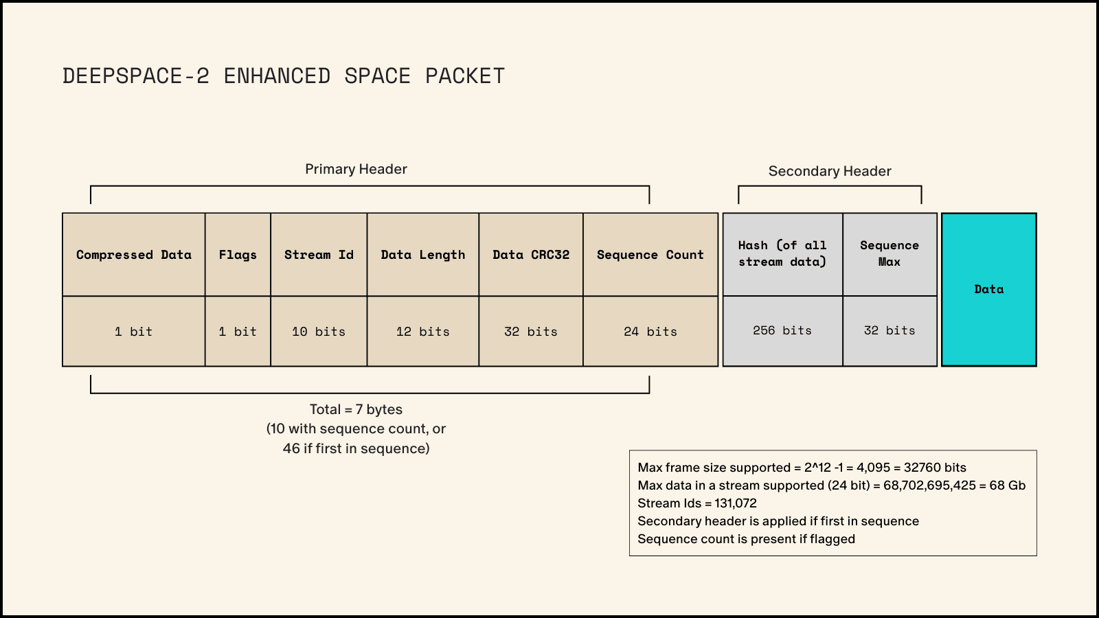
This limitation required us to implement a protocol layer above the RF frames to reassemble data together that might be split across multiple frames by the Vulcan radio. We initially used the CCSDS Space Packet protocol but needed a solution that would also support uploading and downloading large files within the same data stream. As a result, we created our own custom space packet protocol based on the official CCSDS standard.
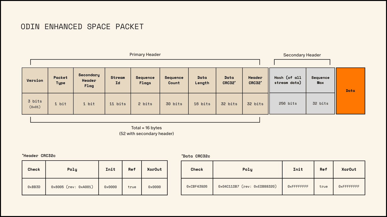
This space packet protocol enabled highly asynchronous downloads and uploads. Both the ground station and spacecraft maintained a database in non-volatile memory of all received space packets. Files were broken into multiple space packets, collectively called a stream. During transmission, if any chunks were corrupted or missing, we could request retransmission of specific chunks without following a strict sequence. This asynchronous approach was essential for our very limited and potentially unreliable data link.
To ensure data integrity, all chunks were protected against corruption by a CRC32 (Cyclic Redundancy Check). Before chunking, all data was hashed with SHA256. Upon completing a stream, all data chunks were aggregated and verified against that hash, providing an extra layer of corruption resiliency.
DeepSpace-2
With DeepSpace-2, we have much more control over the RF framing of data packets and can ensure that a single space packet won’t be split across frames. This allows us to streamline the protocol used in Odin, reducing overhead.
The chunking system, used mainly during large uploads and downloads, will remain mostly the same for DeepSpace-2. However, because our data is guaranteed to align with RF frames, we have much better chances of recovering data from partial frames.
Using compression
The data rate is extremely limited on both spacecraft. To put this in perspective: a typical spacecraft in Low-Earth orbit has a data rate right around 1Gbps. Let’s examine a familiar image, the Mona Lisa.

From LEO, assuming 1Gbps, this image takes 20ms to download. At Odin’s 2kbps data rate, the same image would take 2 hours and 24 minutes.
Additionally, we would need to pay for a large dish antenna for about 3 hours just to download this single image. This was the data transmission challenge we faced.
Odin
We implemented two major solutions for data handling on Odin. First, we made all telemetry data configurable. During testing, whether on our Hardware-in-the-Loop (HITL) system or when debugging the spacecraft, we could enable all data streams for comprehensive visibility.
Second, we compressed all telemetry data. Compression dramatically reduced the size of data requiring downlink. For example, applying our compression technique to the Mona Lisa image above reduced its size to 90.45%. This shortened the download time to just 15 minutes, saving time, increasing data throughput, and reducing costs.
The problem with our compression algorithm was that it required the complete compressed data set for decompression. Partial decompression was impossible.
The assumption with Odin was that this wouldn’t pose a significant issue. A full compressed telemetry packet only required a few radio frames, taking mere seconds of transmission time. If multiple frames proved problematic, we could reconfigure telemetry to fit within a single frame.
This assumption turned out to be wrong. We encountered significant stability problems with the flight computers, Vulcan radio, or power system, and only received two sporadic transmissions from the spacecraft. These transmissions were significantly degraded — from what we believe was a three-frame packet, we could only decode a single frame. Since this data was compressed, we needed all three frames to decompress and extract any information.
Consequently, the only transmission we received from Odin yielded no telemetry data and revealed very little about the state of the spacecraft.
We can see this packet has a sequence count of 1. We knew most telemetry bursts from the spacecraft would consist of 3 packets, meaning we missed packets 0 and 2 from this transmission. This telemetry burst also had a stream ID of 1, indicating it was likely the first burst sent after booting. Stream IDs started at 1, incremented once per second, and wrapped back to 1 after reaching 2,047.
DeepSpace-2
With DeepSpace-2, we want to ensure that during any off-nominal state, every bit of decodable data we downlink contains useful information that will tell us something about the state of the spacecraft, allowing us to take any necessary recovery actions.
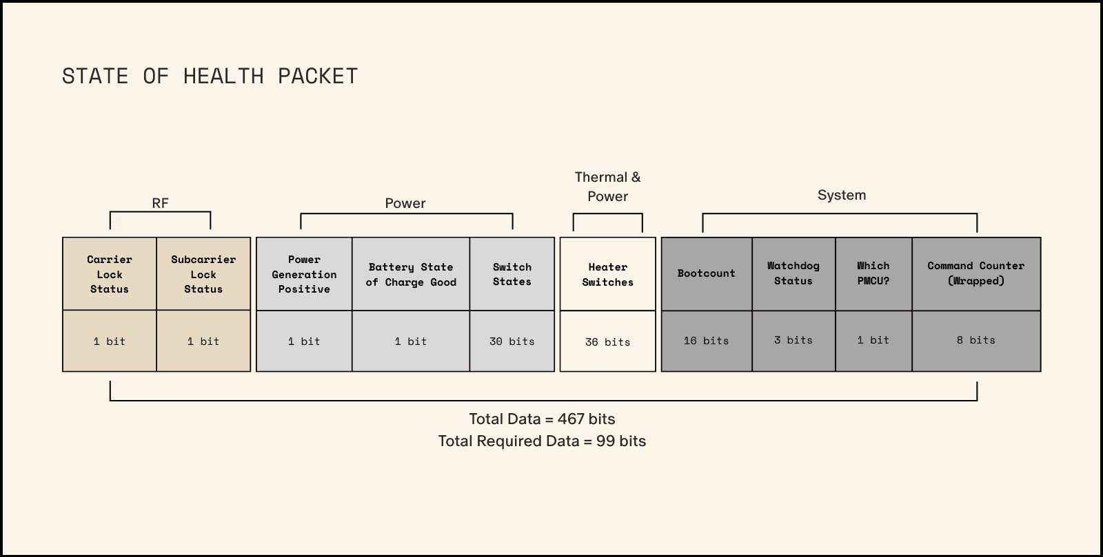
DeepSpace-2 doesn’t even require a flight computer to transmit telemetry data. The power management microcontroller (PMCU) can independently send basic telemetry through a State of Health (SOH) packet. This data is intentionally encoded simply and kept small — just 13 data bytes.
We calculated this specific data size based on how much information we could transmit during a single antenna arc at maximum recoverable spin rate. This design ensures that we can likely receive a complete SOH packet even if the spacecraft is spinning uncontrollably.
The simple encoding provides another advantage: even with partial SOH packet reception, we can potentially guess the missing contents or use brute force compute to extrapolate packets that match a received CRC.
The SOH Packet
Once a flight computer successfully boots, ground commands can be sent to initiate the flow of complete spacecraft telemetry. Like Odin, this telemetry is highly configurable, allowing operators to adjust settings in real time to prioritize the most critical data within their limited bandwidth. However, SOH packets will continue to be intermixed with this full-rate telemetry as a safeguard in case the spacecraft encounters sudden, unexpected problems.
By default, DeepSpace-2's telemetry will not be compressed. If the spacecraft operates nominally, operators can enable compression to achieve a higher effective data rate.
RF Chain
Odin’s Radio System
The Odin spacecraft carried two identical transponder strings onboard. A transponder is a radio that can transmit, receive, and provide ranging data. Odin also had a backup transmitter (transmit only, no receive) that could broadcast at significantly higher power than the transponders. We selected all components for Odin’s radio system based on what we could acquire within a three-month delivery window, due to the spacecraft’s incredibly tight assembly, integration, and test schedule.
Below is a diagram showing the Odin Radio Architecture. Each component will be outlined below.
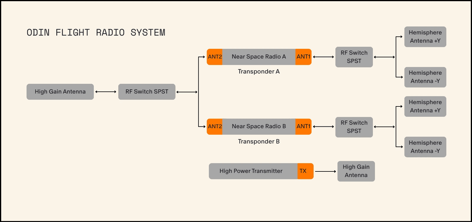
The two transponder chains are identical. Each transponder has two antenna feeds (ANT1 and ANT2), with only one active at a time. Each feed handles both transmission and reception simultaneously. The transponder includes a built-in power amplifier that boosts the transmitter signal to a maximum of 4W. At this power level, we calculated our downlink budget would close at distances over 2 million miles using our hemisphere antennas, and even farther with the high gain antennas. At the time, no suitable power amplifiers were available for the RF chain without significant design implications. We simply lacked margin in both mass budget and schedule for a more powerful RF architecture. Since the link budget closed to the asteroid’s distance (with some caveats), we determined this was sufficient.
Inside the Odin Transponder, an RF switch directed the signal between the ANT1 and ANT2 feeds, allowing us to select the active antenna. Each radio had a dedicated RF chain on its ANT1 port. This ANT1 connection fed into an external RF switch that toggled between hemispherical antennas on the +Y and -Y faces. This 1-in, 2-out switch connected the single ANT1 feed to two different antennas. We selected hemisphere antennas for their wide field of view, enabling link closure even when not directly pointed at the Earth station. However, only one antenna could function at any time — either +Y or -Y, never both. Our flight software periodically switched between the two side antennas to maximize the spacecraft’s overall view factor.
The ANT2 feeds from both transponders connected to another RF switch. This 2-in, 1-out switch allowed communication from either transponder to the shared high gain antenna. To use this antenna, the selected radio needed to be switched to ANT2, and the high gain RF switch needed to select that radio. The high gain antenna offered significantly greater Earth communication range, though with much stricter pointing requirements. A critical flaw in this architecture was that the unused port on this RF switch lacked termination. This meant that if both radios transmitted on their ANT2 feeds simultaneously, only one feed would be connect to an antenna. The unterminated radio would have nowhere to direct its signal power, potentially damaging radio components beyond repair.
While the RF switches on Odin conveniently enabled multiple RF chains, they had a significant drawback: they provided no telemetry. This made it impossible to verify which RF chain was active at any moment, leaving both spacecraft and operators uncertain about the vehicle’s current configuration.
Beyond the two transponders, we included a high-power backup transmitter capable of 20W output — significantly more powerful than the transponders. This transmit-only unit had its own dedicated high gain antenna and could downlink data at much higher rates than the transponders ever could. We designated this as our primary path for downlinking asteroid imagery during the flyby.
In summary, Odin’s RF system had several serious limitations: directional constraints (only one direction at a time), unmeasurable switches, and relatively low-power transmitters. These factors collectively restricted the system’s effectiveness and range.
DeepSpace-2's Radio System
For DeepSpace-2, we adopted a different approach. Drawing from our previous experience, we recognized the need for greater transmit power and flexibility than we had with Odin.
Below is a diagram showing the RF Architecture of the DeepSpace-2 Space Vehicle.
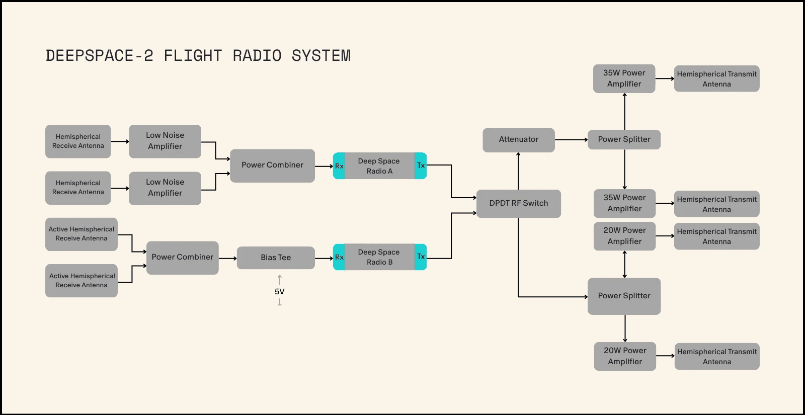
DeepSpace-2 has some pretty critical differences than Odin in terms of RF components. First, we eliminated the backup transmitter entirely, leaving just two radios on the spacecraft: Deep Space Radio A and Deep Space Radio B. Each has fully independent receive chains using different technologies from separate vendors. A critical distinction between DeepSpace-2 and Odin transponders is that DeepSpace-2's Deep Space Radios have separate transmit (Tx) and receive (Rx) ports, while Odin’s transponders had bidirectional antenna feeds (ANT1 and ANT2) handling both Tx and Rx functions. This separation allows us to optimize both our uplink and downlink chains for our specific asteroid hunting mission requirements.
Deep Space Radio A employs hemispherical antennas with 50dB Low Noise Amplifiers, while Deep Space Radio B uses active receive antennas. Though the B-side receive antennas aren’t as powerful as the A-Side, both meet the mission’s uplink range requirements. Both radio receive chains have antennas facing the +Y and -Y directions of the vehicle. Unlike on Odin, DeepSpace-2's radios listen in both directions simultaneously through an RF Power Combiner — a device that merges two RF channels into one. This improvement eliminates concerns about the spacecraft’s listening direction, as DeepSpace-2 continuously monitors all possible directions.
For transmission, each side has a dedicated component chain consisting of power splitters and power amplifiers. Between the radios and their respective transmit chains sits a Double Pole Double Throw (DPDT) RF Switch. This switch enables either radio to use either transmit chain, creating resilience against failures. If the A-side power amplifiers fail, the the A-side radio can switch to using the B-side chain, if needed. The DPDT switch also provides valuable telemetry data, allowing the flight computer to determine the switch’s state with certainty, ensuring we always know the RF system’s configuration.
Both transmit chains share similar designs. They use power splitters (the opposite of power combiners, dividing one signal into two with half the power each) to split the transmit channel into two feeds. One feed connects to a power amplifier on the +Y side, while the other connects to an amplifier on the -Y side. Unlike Odin, DeepSpace-2 doesn’t switch between sides — the transmitted signal goes to both antennas simultaneously, eliminating any guesswork about the spacecraft’s orientation. The main difference between the two transmit chains is amplifier power. The A-side uses 35W amplifiers, while the B-side uses 20W amplifiers — a choice made to balance mass savings with component diversity.
This architecture resolves the power limitations and operational complexities we faced with Odin, emphasizing robustness and redundancy. We’ve eliminated guesswork in determining the RF switch state, increased transmission power to 5-9 times that of Odin, and made the platform more omnidirectional for both receiving and transmitting. Additionally, the DeepSpace-2 RF system is designed to prevent self-damage, as every transmit chain always terminates in an antenna.